Tag Archives: Pi 5

AI on the Edge LESSON 52: Gesture Recognition on the Raspberry Pi 5

Welcome back, everyone! In today’s lesson, AI on the Edge LESSON 52: Gesture Recognition on the Raspberry Pi 5, we are building a custom, real-time hand gesture recognition system from scratch. Up until now, we have been using MediaPipe to track keypoints, identify individual hand joints, and extract raw 3D coordinate data. But raw coordinates alone don’t tell the computer what your hand is actually doing. Today, we bridge that gap by teaching our Raspberry Pi 5 how to train on custom hand positions and dynamically classify live hand gestures using pure mathematics and vector geometry—no heavy neural network retraining required.

The core secret to making gesture recognition work reliably across different camera distances is scale-invariant distance normalization. If you simply measure the pixel distance between your fingertips and your wrist, bringing your hand closer to the camera lens will blow out those numbers and break your classifier. To solve this, our script establishes a baseline unit of measurement for every single frame: the distance between the wrist (landmark 0) and the index finger base joint (landmark 5). By dividing all measured finger-tip-to-wrist and tip-to-tip distances by this dynamic scale factor, the resulting feature vector remains identical whether your hand is two feet away or five feet away from the lens.

Once we extract this normalized 15-element feature vector—representing the spatial ratios between all five fingertips relative to the wrist and each other—we construct an interactive training phase directly inside the live video loop. The program prompts you in the terminal for the number of custom gestures you wish to record, along with their labels (such as “Peace”, “Thumbs Up”, or “Fist”). As you present each gesture to your camera feed and press the spacebar, the algorithm captures the instantaneous geometric signature of your hand and stores it in a runtime training dictionary.

During live inference, our classifier calculates the Sum of Absolute Errors (SAE), or Manhattan distance, between the live incoming feature vector and every stored profile in our training dataset. The function loops through all saved gestures to find the candidate with the absolute lowest cumulative error score. To prevent false positives when an untrained or messy hand pose is shown, we compare that lowest error score against a strict threshold value (maxErrorThreshold = 3.5). If the error falls within the allowable boundary, the matched gesture label is instantly displayed on the live OpenCV HUD; otherwise, the system safely defaults to “Unknown”.

We manage our camera feed using high-speed frame capture with Picamera2 running at 60 frames per second at 1280×720 resolution, processing hand detection with MediaPipe Hands, and rendering real-time performance diagnostics—including an exponential moving average FPS counter—directly onto the video output. Go ahead, study the methodology, load the concept onto your Raspberry Pi 5, grab a hot cup of coffee, and let’s get building!


AI on the Edge LESSON 47: Emotion Detector Using MediaPipe, OpenCV and Raspberry Pi

In this exciting lesson, we build a real-time Emotion Detector that can recognize basic human emotions using just a Raspberry Pi, a camera, and the power of MediaPipe. The system watches your face and identifies whether you look Neutral, Smiling, Surprised, or Angry — and then reacts instantly by changing the color of a NeoPixel ring and displaying the detected emotion on both the camera preview and a small OLED display.Using MediaPipe’s Face Mesh solution, the program tracks 468 facial landmarks in real time. From these points, we carefully calculate key facial ratios — such as eye openness, mouth width, and mouth height relative to head width. These measurements allow us to create simple but effective rules that distinguish between different emotional expressions. For example, a wide mouth combined with raised cheeks indicates a smile, while a small mouth opening and narrowed eyes suggests anger.The project beautifully integrates several powerful technologies:

  • Picamera2 for high-performance camera capture
  • OpenCV for image processing and on-screen text display
  • MediaPipe Face Mesh for accurate facial landmark detection
  • NeoPixel RGB ring that lights up in different colors depending on the detected emotion
  • SSD1306 OLED display that shows both the emotion name and a simplified wireframe of your face

One of the most satisfying parts of this project is seeing the NeoPixel ring instantly change color to match your emotion — green for happy, cyan for surprised, red for angry, and yellow for neutral. The OLED also mirrors the detected emotion, making the entire system feel alive and responsive.This lesson is a fantastic step forward in understanding how to combine computer vision with physical outputs on the edge. You will learn how to extract meaningful measurements from facial landmarks, build rule-based emotion logic, and synchronize visual feedback across multiple devices (camera preview, NeoPixel, and OLED).By the end of Lesson 47, you will have a working real-time emotion recognition system running entirely on a Raspberry Pi — a great foundation for more advanced projects like mood-reactive lights, interactive robots, or even assistive technology.

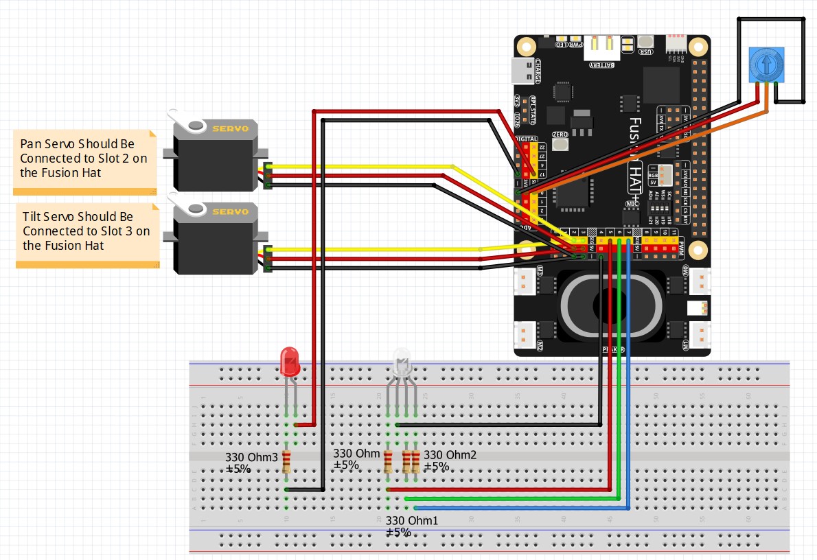
These are the schematics we are using for todays project. If you are taking the class, you should already have these components connected:

Fusion Hat Circuit Diagram
This is the circuit we will use moving forward in the class
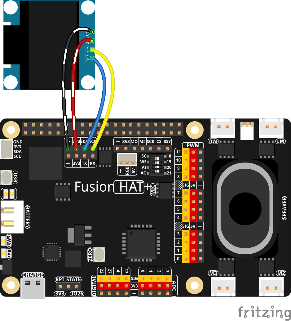
OLED
SSD1306 OLED Connected to the Fusion AI Hat
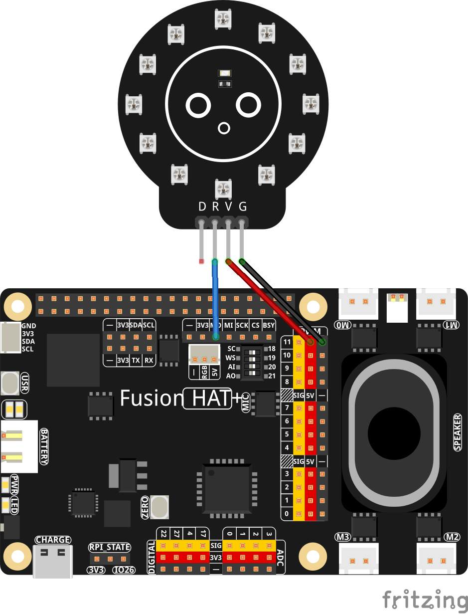
NeoPixel
NeoPixel Schematic

AI on the Edge LESSON 41: Creating FaceMesh Using MediaPipe in OpenCV

In this project, I demonstrate how to create a smooth, real-time face mesh overlay using the Raspberry Pi 5, the official Pi Camera, MediaPipe, and OpenCV. The program captures live video from the camera and draws a detailed, colorful mesh that follows every movement of the face with high accuracy. The result is a visually appealing augmented reality-style effect that runs efficiently even on a single-board computer.

The goal of this project is to build a responsive face tracking system that detects and draws 468 facial landmarks in real time. This creates a striking mesh that highlights the contours of the face, eyes, lips, and jawline, making it an excellent foundation for more advanced computer vision projects like virtual filters, AR effects, or interactive installations.

The program follows a straightforward but efficient real-time vision pipeline. First, it initializes the Raspberry Pi Camera using the modern picamera2 library, configured for 1280×720 resolution at 60 frames per second. It then sets up MediaPipe’s Face Mesh solution with landmark refinement enabled for better eye tracking.

In the main loop, the program continuously grabs a frame from the camera, corrects its orientation, and converts it from BGR to RGB format since MediaPipe expects RGB input. The frame is then passed to the Face Mesh model for processing. When a face is detected, the program draws multiple layers of graphics on top of the image: a fine tesselation mesh across the entire face, thick and vibrant contours around the major facial features, and special highlighting on the irises. Finally, the processed frame is displayed in an OpenCV window, creating a smooth and engaging real-time visualization.

This approach works particularly well on the Raspberry Pi 5 because it balances visual quality with performance. By limiting detection to a single face and using efficient drawing methods, the application maintains high frame rates while producing a professional-looking result. The multi-layer drawing technique (tesselation + contours + irises) gives the mesh depth and visual appeal that single-pass drawings often lack.

The project makes use of several powerful technologies: picamera2 for fast camera access, Google’s MediaPipe for high-speed machine learning-based landmark detection, OpenCV for image handling and display, and NumPy for efficient array operations.

This face mesh project serves as an excellent stepping stone into real-time AI and computer vision on embedded hardware. Once you have the basic mesh working, it becomes much easier to expand into creative applications such as face filters, gesture recognition, or overlaying the mesh onto other video sources.

The code developed in the video lesson is presented below:


AI on the Edge LESSON 27: Track Objects of Interest in OpenCV Using Contours

AI on the Edge LESSON 27: Track Objects of Interest in OpenCV Using Contours

Hey everyone, Paul McWhorter here from TopTechBoy.com. Welcome back to our channel, where we learn to build real, intelligent systems on edge hardware. Grab yourself a nice hot cup of coffee or a cold glass of iced tea, because today we are taking a massive leap forward in our computer vision journey.

Up until now, we have learned how to configure our cameras, calculate frame rates smoothly, and isolate specific objects based on color using the HSV color space. We built beautiful masks and composite images that show only our target color. But let’s be honest with ourselves: a mask is just a collection of white pixels on a black screen. The computer doesn’t actually know where the object is, how big it is, or how to follow it if it moves.

In this lesson, we are going to fix that. We are going to teach the machine to look at our mask, isolate the single biggest shape of interest, ignore the background noise, and draw a real-time bounding tracking box around it. This is true object tracking.

The Core Concept: What is a Contour?

Think of a contour as a mathematical boundary line. When OpenCV looks at a binary mask (where your target object is white and everything else is black), a contour is the continuous line that traces the outer edge of that white shape.

The beauty of contours is that they turn a chaotic cloud of thousands of isolated pixels into structured, manageable vector shapes. Once OpenCV finds these shapes, it can calculate their physical properties, such as their area, perimeter, and exact center.

The Three Steps to Algorithmic Object Tracking

To turn a raw camera frame into a fully tracked target, our script follows a strict three-part engineering pipeline inside our main execution loop:

1. Extracting Every Boundary

First, we pass our binary mask into OpenCV’s contour detection engine. We configure it to use external retrieval, meaning it will ignore any hollow holes inside the object and only trace the outermost boundary. It returns a list of every single contour it finds in the frame.

2. Hunting for the Largest Target

In the real world, your camera view is never perfectly clean. Even with an excellent HSV color mask, you will get random speckles, reflections, or background noise showing up as tiny white dots on your mask. If we tried to track everything, our program would lose its mind. To solve this, we use a Python maximization function to scan our list of contours and extract the absolute largest one based on its physical area.

3. Setting an Area Noise Floor

Even after finding the largest contour, what happens if your object completely leaves the camera view? The largest remaining “object” might be a tiny, single-pixel spec of static noise on the edge of the screen. To prevent our tracking box from jumping around erratically, we establish a strict structural threshold—a noise floor. If the area of the largest contour isn’t big enough to confidently be our target, we ignore it completely.

Drawing the Bounding Box

Once we have successfully isolated our valid, large contour, we don’t just want to draw a messy, squiggly line around it. We want clean coordinates that an automation system or a robotic pan-tilt kit could actually use to follow the target.

We pass our largest contour into a bounding rectangle function. OpenCV automatically calculates the exact mathematical limits of that shape and returns four precise numbers:

    • X: The horizontal starting pixel coordinate of the object.

    • Y: The vertical starting pixel coordinate of the object.

    • W: The total width of the object in pixels.

    • H: The total height of the object in pixels.

With those four dimensions locked down, we use a standard drawing function to overlay a crisp, green rectangle directly onto our live color camera feed. Now, as you move your object around the room, the box follows it dynamically, tracking its position in real time at high frame rates.

Note you will have to tune the LC and UC parameters for your object of interest, as we showed last week.


AI on the Edge LESSON 24: Processing Mouse Events in OpenCV on Pi 5

Welcome back, everyone! In our last lesson, we learned how to use matrix slicing to hardcode a Region of Interest (ROI) into our frames. That was a great static approach, but today we are taking interactivity to a whole new level.

In this lesson, you are going to learn how to catch Mouse Events inside your OpenCV windows. Instead of guess-and-checking coordinates in your code, you will be able to click anywhere on your live video stream to instantly grab the precise (x, y) pixel coordinates and read the exact color value of the pixel right under your mouse pointer. This is the foundational mechanic you need to build interactive, point-and-click AI applications.

The Core Concept: Mouse Callbacks and Global Frames

To listen for mouse clicks or movement, OpenCV uses what is called a Callback Function. You tell OpenCV: “Hey, keep an eye on this specific window. If the user does anything with the mouse inside it, instantly jump over to my custom function and tell me what happened.”

We set this up using:

cv2.setMouseCallback(‘Camera’, mouseAction)

The [y, x] Matrix Inversion Trap

There is a massive mathematical trap that catches almost every beginner when they start mapping mouse clicks to image matrices:

  • OpenCV Mouse Coordinates: When you move your mouse, OpenCV tracks position using standard Cartesian geometry: (x, y), where x is the column (horizontal distance from the left) and y is the row (vertical distance from the top).

  • NumPy Array Coordinates: When you plug those numbers into your image array to inspect a pixel, NumPy expects matrix indexing: [row, column].

Because rows correspond to the height (y) and columns correspond to the width (x), you must always invert the coordinates when accessing the frame array:

If you try to pass frame[x, y], your program will either crash with an “index out of bounds” error or return data from the completely wrong part of the image!

The Python Code Developed in This Lesson

Here is the complete, streamlined script we built during today’s tutorial. Copy this code into your workspace on your Raspberry Pi 5, fire it up, and watch your terminal output as you click around the video window.

We first developed this program as a simple example of processing mouse clicks, and print the detected event:

In order to make the program more useful, we developed this code that monitors the position of the mouse cursor, and reports the color of the pixel the mouse points at. The values are printed as labels on the openCV frame:

We can now take the project to the next level by setting the LED color to the color pointed at by the cursor in the openCV window. We will be using our standard circuit we have used in the earlier lessons.

Fusion Hat Circuit Diagram
This is the circuit we will use moving forward in the class

This is the code we developed to set the LED color based on the pixel position of the cursor in the openCV window.

Homework Assignment

Alright, it’s time to put this knowledge to work. Your homework assignment is to turn this simple reporting tool into an interactive, dynamic ROI selector. The homework is to  first create a text display under the FPS on the frame that show RGB value at the pixel position the mouse is pointing at, and the pixel location.

 Your homework assignment is to turn this simple reporting tool into an interactive, dynamic ROI selector.

  1. Start with your clean 1280×720 live camera stream.

  2. Modify your mouseAction callback function to look for specific mouse clicks.

  3. The Target Mechanic: When you Left-Click on the video window, store those specific coordinates as your upper-left corner. When you release the click, store those coordinates as your lower-right corner. As you are selecting, draw a live box outline over your ROI

  4. Using those two dynamic coordinate sets, use matrix slicing to pull a clean Region of Interest (ROI) out of the frame and instantly display it in a completely separate, standalone window called “Target ROI”.

  5. Safety Requirement: Make sure your code can handle clicks in any order without crashing (e.g., if a user right-clicks higher or further left than their left-click, write the conditional logic to sort the indices properly before slicing).

Get your black coffee ready, write your logic step-by-step from scratch, and do not copy code you can’t explain. Post your homework solution video on YouTube and drop a link in the comments section below so I can see who is running with the big dogs!