Well, hello there! I’m absolutely delighted you could join me today. If you’ve been following along with our journey into AI on the Edge, you know that we are getting closer and closer to building some truly powerful, real-world computer vision applications. But before we can get to the fancy AI stuff, we have to master the fundamentals. Today, we’re tackling something that is going to make your projects look—and feel—a whole lot more professional: creating a Region of Interest (ROI) using the mouse.
Why Do We Need an ROI?
Think about it. When you’re processing a video feed, you’re usually wasting a ton of compute power looking at things that don’t matter. Maybe you’re tracking a ball on a table, but your camera is seeing the whole room. Why process the walls and the ceiling when you only care about the table? By defining an ROI, we tell our code: “Ignore everything else. Only look here.” It saves processing time, it reduces noise, and it makes your AI much more accurate.
Interacting with OpenCV
In this lesson, we’re going to step beyond simple static code. I’m going to show you how to use OpenCV’s callback functions to make your program “live.” We’ll use the mouse to click and drag a rectangle directly on the video feed to define our ROI in real-time. It’s interactive, it’s intuitive, and it’s a vital skill for anyone building real-world vision systems.
The Code
Now, I’ve put a lot of work into making this code clean and easy to follow. You’ll see exactly how we capture those mouse events—cv2.EVENT_LBUTTONDOWN, cv2.EVENT_MOUSEMOVE, and cv2.EVENT_LBUTTONUP—to create that bounding box dynamically.
|
1 2 3 4 5 6 7 8 9 10 11 12 13 14 15 16 17 18 19 20 21 22 23 24 25 26 27 28 29 30 31 32 33 34 35 36 37 38 39 40 41 42 43 44 45 46 47 48 49 50 51 52 53 54 55 56 57 58 59 60 61 62 63 64 65 66 67 68 69 70 71 72 73 74 75 76 77 78 79 80 81 82 83 84 85 86 87 88 89 90 91 92 93 94 95 96 97 98 99 100 101 102 103 104 105 106 107 108 109 110 111 112 113 114 115 116 |
import cv2 import time from picamera2 import Picamera2 from fusion_hat.pwm import PWM piCam = Picamera2() W=1280 H=720 tStart = time.time() fps = 0 redPin = 5 greenPin = 6 bluePin = 7 redLED = PWM(redPin) greenLED = PWM(greenPin) blueLED = PWM(bluePin) RES = (W,H) piCam.preview_configuration.main.size = RES piCam.preview_configuration.main.format = "RGB888" piCam.preview_configuration.controls.FrameRate=60 piCam.preview_configuration.align() piCam.configure("preview") piCam.start() textLowerLeft = (int(W*.01),int(H*.06)) fontFace = cv2.FONT_HERSHEY_SIMPLEX fontThickness = int(W/425) fontScale = H*.0015 fontColor = (0,0,255) textLowerLeft1 = (int(W*.01),int(H*.06)*2) textLowerLeft2 = (int(W*.01),int(H*.06)*3) xPos = 0 yPos = 0 valR = 0 valG = 0 valB = 0 frame = None drawing = False startX = 0 endX = 0 makeROI = False boxColor = (0,255,255) boxThick = 3 def mouseAction(event, x, y, flags, param): global frame, xPos, yPos, valR, valG, valB global drawing, makeROI, startX, startY, endX, endY if event == 0: xPos = x yPos = y if frame is not None: valB, valG, valR = frame[y,x] redLED.pulse_width_percent(int(valR/255*100)) greenLED.pulse_width_percent(int(valG/255*100/2)) blueLED.pulse_width_percent(int(valB/255*100/4)) if drawing == True: endX = x endY = y if event == 1: drawing = True makeROI = False startX = x startY = y endX = x endY = y if event == 4: drawing = False makeROI = True endX = x endY = y cv2.namedWindow('Camera') cv2.moveWindow('Camera',0,65) cv2.setMouseCallback('Camera',mouseAction) print("Click and Drag to Draw a Box") print("Release Mouse to Finalize box. Press q to Quit") while True: deltaT = time.time() - tStart tStart=time.time() fps = fps*.95 + (1/deltaT)*.05 frame= piCam.capture_array() frame=cv2.flip(frame,-1) if drawing == True: cv2.rectangle(frame,(startX,startY),(endX,endY),boxColor,boxThick) if makeROI == True: ROI = frame[startY:endY,startX:endX] ROIgray = cv2.cvtColor(ROI,cv2.COLOR_BGR2GRAY) cv2.imshow("ROI",ROI) cv2.imshow("ROIgray",ROIgray) cv2.moveWindow("ROI",W,65) cv2.moveWindow("ROIgray",W,endY-startY+200) myText = "FPS: "+str(round(fps,1)) cv2.putText(frame,myText,textLowerLeft,fontFace,fontScale,fontColor,fontThickness) text1 = "Mouse Pos: "+str((xPos,yPos)) text2 = "Pixel Color: "+str((valR,valG,valB)) cv2.putText(frame,text1,textLowerLeft1,fontFace,fontScale,fontColor,fontThickness) cv2.putText(frame,text2,textLowerLeft2,fontFace,fontScale,fontColor,fontThickness) cv2.imshow("Camera", frame) cv2.moveWindow("Camera",0,60) if cv2.waitKey(1)==ord('q'): break cv2.destroyAllWindows() redLED.pulse_width_percent(0) greenLED.pulse_width_percent(0) blueLED.pulse_width_percent(0) print('Program Terminated') |
Putting It to the Test
I want you to take this code, run it on your Jetson, and play around with it. Try defining different regions. Notice how the frame rate stays steady because we aren’t bogging down the CPU with unnecessary pixels. This is the “Edge” part of “AI on the Edge”—making smart, efficient decisions right where the data is being captured.
I can’t wait to see what you build with this. As always, keep those questions coming, stay curious, and most importantly—don’t get discouraged! We’re doing hard things, and you are doing a great job.
I’ll see you in the next lesson!
What questions do you have about implementing ROI in your own computer vision projects? Post them in comments on the video! Thanks for learning.
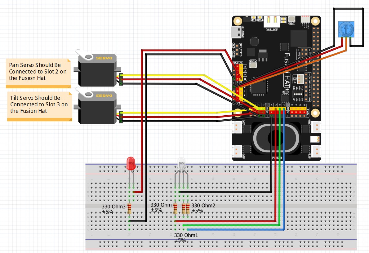
We will be using the circuit used in the earlier lessons: