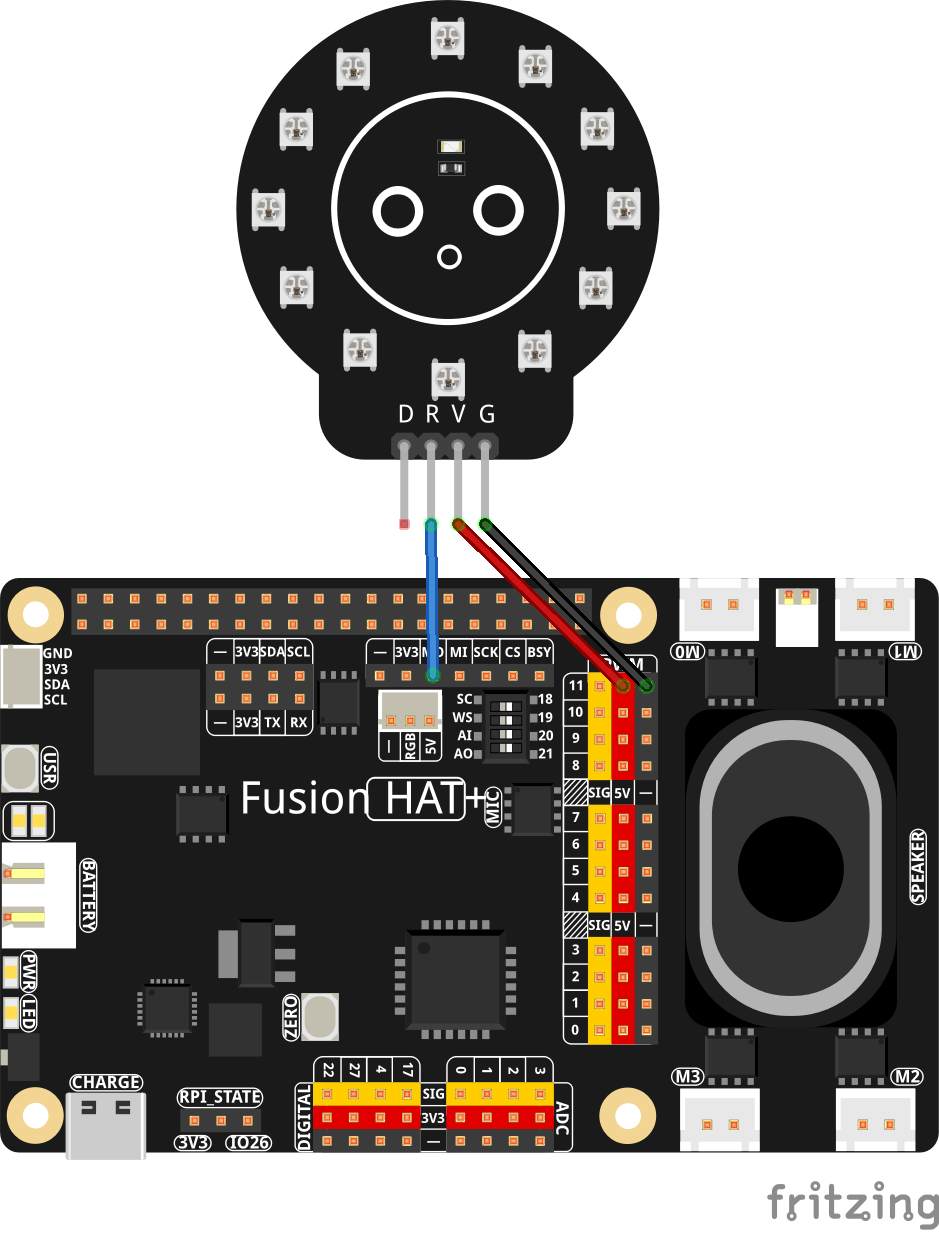
Hey everybody, welcome back to AI on the Edge! In Lesson 50 we’re taking things to the next level — we’re combining real-time hand tracking with a physical NeoPixel ring so you can change colors just by pointing at the screen! Using MediaPipe on the Raspberry Pi, we track your index finger tip and turn the big camera view into an interactive color picker. Hover over any of the seven big colored circles (Red, Green, Blue, Cyan, Magenta, Yellow, or Black) and — boom — the NeoPixel ring instantly lights up with that color!
This lesson is super fun because it finally brings together everything we’ve been building: smooth hand detection, coordinate mapping between camera and OLED, visual feedback, and real-world hardware control. You’ll see your finger tracked with a big blue dot, watch the selected color update live on both the screen and the OLED, and control actual RGB lights with nothing but a gesture.
By the end of this lesson you’ll have a working gesture-controlled color mixer that feels like real interactive magic. This is the kind of project that makes people say “Wow, you built that on a Raspberry Pi?!”
This is also a perfect foundation for even cooler future projects — gesture-controlled lighting, touchless interfaces, interactive games, or even a full gesture-controlled robot or light show.
So grab your Raspberry Pi, hook up that NeoPixel ring, fire up the camera, and let’s start waving our hands around like we’re casting spells! As always, the complete code is right below the video. Watch along, run the code, then start tweaking it — maybe add more colors, make the ring react differently to gestures, or combine it with the hand connection drawing from earlier lessons.I’m really excited to see what you create with this one!Now go make something awesome!
|
1 2 3 4 5 6 7 8 9 10 11 12 13 14 15 16 17 18 19 20 21 22 23 24 25 26 27 28 29 30 31 32 33 34 35 36 37 38 39 40 41 42 43 44 45 46 47 48 49 50 51 52 53 54 55 56 57 58 59 60 61 62 63 64 65 66 67 68 69 70 71 72 73 74 75 76 77 78 79 80 81 82 83 84 85 86 87 88 89 90 91 92 93 94 95 96 97 98 99 100 101 102 103 104 105 106 107 108 109 110 111 112 113 114 115 116 117 118 119 120 121 122 123 124 125 126 127 128 129 130 131 132 133 |
# ==================================================================== # DISCLAIMER: # This code is provided as-is for educational and experimental # purposes only. The author makes no representations or warranties of # any kind concerning the safety, suitability, or accuracy of this # code. Use at your own risk. The author assumes no liability for any # damages, system failures, security breaches, or network issues # resulting from the use or implementation of this script. # ==================================================================== import cv2 import time from picamera2 import Picamera2 import mediapipe as mp import board import adafruit_ssd1306 from PIL import Image,ImageDraw,ImageFont wOLED = 128 hOLED = 64 I2C_ADDRESS = 0x3C i2c = board.I2C() oled = adafruit_ssd1306.SSD1306_I2C(wOLED, hOLED, i2c, addr = I2C_ADDRESS) W=1280 H=720 tStart = time.time() fps = 0 RES = (W,H) piCam = Picamera2(1) piCam.preview_configuration.main.size = RES piCam.preview_configuration.main.format = "RGB888" piCam.preview_configuration.controls.FrameRate=60 piCam.preview_configuration.align() piCam.configure("preview") piCam.start() textLowerLeft = (int(W*.01),int(H*.05)) fontFace = cv2.FONT_HERSHEY_SIMPLEX fontThickness = int(W/425) fontScale = H*.0015 fontColor = (0,0,255) hands = mp.solutions.hands.Hands( model_complexity = 0, min_detection_confidence = .5, min_tracking_confidence = .5, max_num_hands =2) mpDraw = mp.solutions.drawing_utils cv2.namedWindow('Camera',cv2.WINDOW_GUI_NORMAL) cv2.moveWindow('Camera',0,65) cv2.resizeWindow('Camera',W,H) import neopixel_spi as neopixel spi = board.SPI() strip = neopixel.NeoPixel_SPI(spi, 12, pixel_order=neopixel.GRB,auto_write=False) strip.fill(0) strip.show() xStart=int(W/2) yStart=int(H/10) margin=100 radius=25 radiusOutline=30 radiusFlash=35 boxW = 4*radius boxH =int(.75*boxW) xSpace= int((W-2*margin)/2/3) colorDot= [(xStart-3*xSpace,yStart),(xStart-2*xSpace,yStart),(xStart-xSpace,yStart),(xStart,yStart),(xStart+xSpace,yStart),(xStart+2*xSpace,yStart),(xStart+3*xSpace,yStart)] oledPOS=[] for dot in colorDot: oledPOS.append((int(dot[0]/W*wOLED),int(dot[1]/H*hOLED*.4))) oledText = ['R','G','B','C','M','Y','B'] colorLabel = 'B' colors =[(0,0,255),(0,255,0),(255,0,0),(255,255,0),(255,0,255),(0,255,255),(0,0,0)] xBox = xStart-3*xSpace yBox = int(yStart*1.5) boxUpperLeft = (int(xBox-radius-boxW/4),yBox) boxLowerRight = (int(xBox-radius-boxW/4+boxW),yBox+boxH) colorActive =(0,0,0) inCircle = False while True: deltaT = time.time() - tStart tStart=time.time() fps = fps*.95 + (1/deltaT)*.05 frame= piCam.capture_array() frame=cv2.flip(frame,-1) frame=cv2.flip(frame,1) image = Image.new('1',(wOLED,hOLED)) draw = ImageDraw.Draw(image) for i in range(7): if inCircle: cv2.circle(frame,colorDot[i],radiusFlash,(255,255,255),-1) cv2.circle(frame,colorDot[i],radiusOutline,(200,200,200),-1) cv2.circle(frame,colorDot[i],radius,colors[i],-1) draw.text(oledPOS[i],oledText[i],fill=255) cv2.rectangle(frame,boxUpperLeft,boxLowerRight,colorActive,-1) rgbFrame= cv2.cvtColor(frame, cv2.COLOR_BGR2RGB) handResults = hands.process(rgbFrame) if handResults.multi_hand_landmarks: for myHands in handResults.multi_hand_landmarks: landMarks = myHands.landmark x = int(landMarks[8].x*W) y = int(landMarks[8].y*H) xOLED = int(landMarks[8].x*wOLED) yOLED = int(landMarks[8].y*hOLED) cv2.circle(frame,(x,y),10,(255,0,0), -1) draw.ellipse((xOLED-3,yOLED-4,xOLED+3,yOLED+4),fill=255) cnt = 0 for pos in colorDot: if abs(x-pos[0])<radius and abs(y-pos[1])<radius: colorActive=colors[cnt] colorLabel =oledText[cnt] #draw.text((int(wOLED/2),int(hOLED/2)),oledText[cnt],fill=255) strip.fill((colorActive[2],colorActive[1],colorActive[0])) strip.show() cnt=cnt+1 draw.text((int(wOLED/2),int(hOLED/2)),colorLabel,fill=255) oled.image(image) oled.show() myText = "FPS: "+str(round(fps,1)) cv2.putText(frame,myText,textLowerLeft,fontFace,fontScale,fontColor,fontThickness) cv2.imshow("Camera", frame) cv2.moveWindow("Camera",0,60) if cv2.waitKey(1)==ord('q'): break cv2.destroyAllWindows() print('Program Terminated') |
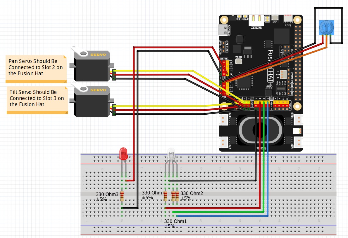
This is the core circuit we use for the class:
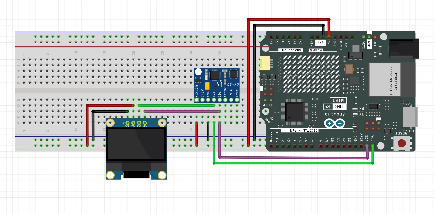
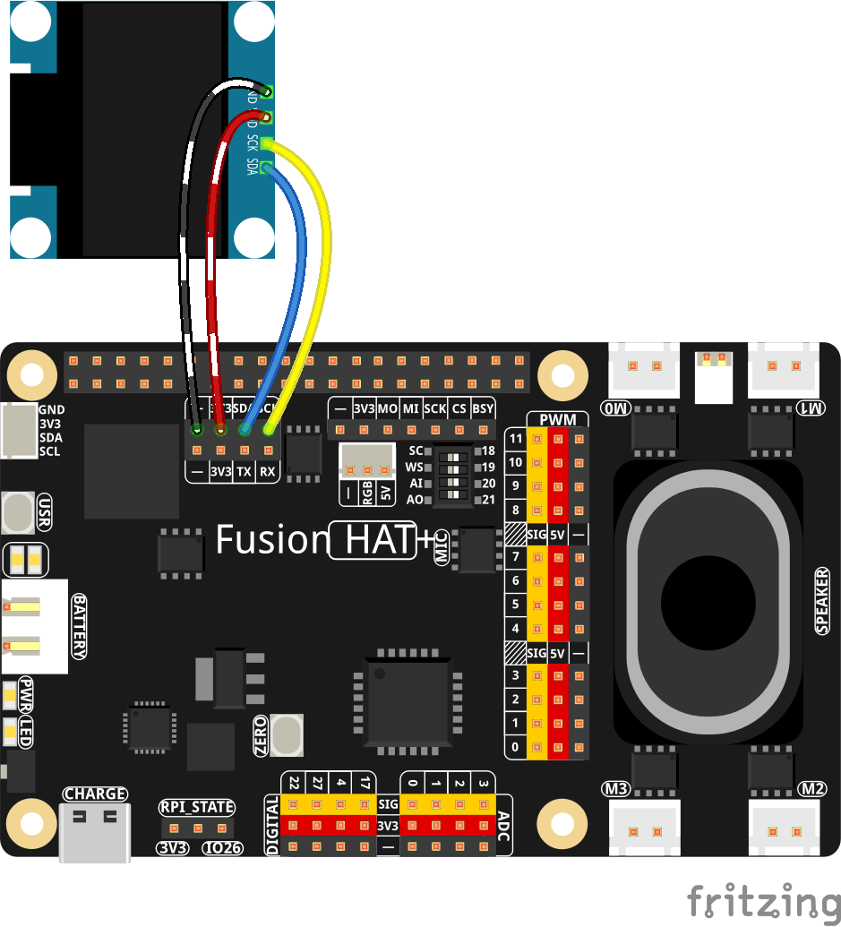
This is the schematic to add the OLED:
Then this is the schematic to add the NeoPixel