
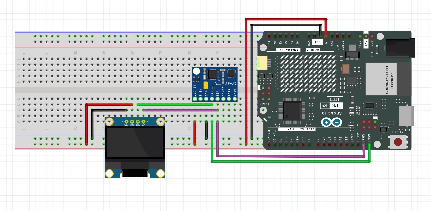
In this video lesson we wrap up our project to create an Arduino IMU using the GY-87 IMU module, with an MPU6050 chip and a QMC5883L Magnetometer. In this lesson we complete the avionics display, creating an accurate graphical output for Roll, Pitch, and Yaw. This is the schematic we are using for this project:
This is the code we develop in the video. Remember, you have to calibrate your sensors, and put your calibration numbers into the code below. I showed you how to do the calibration in THIS LESSON.
|
1 2 3 4 5 6 7 8 9 10 11 12 13 14 15 16 17 18 19 20 21 22 23 24 25 26 27 28 29 30 31 32 33 34 35 36 37 38 39 40 41 42 43 44 45 46 47 48 49 50 51 52 53 54 55 56 57 58 59 60 61 62 63 64 65 66 67 68 69 70 71 72 73 74 75 76 77 78 79 80 81 82 83 84 85 86 87 88 89 90 91 92 93 94 95 96 97 98 99 100 101 102 103 104 105 106 107 108 109 110 111 112 113 114 115 116 117 118 119 120 121 122 123 124 125 126 127 128 129 130 131 132 133 134 135 136 137 138 139 140 141 142 143 144 145 146 147 148 149 150 151 152 153 154 155 156 157 158 159 160 161 162 163 164 165 166 167 168 169 170 171 172 173 174 175 176 177 178 179 180 181 182 183 184 185 186 187 188 189 190 191 192 193 194 195 196 197 198 199 200 201 |
#include <Adafruit_MPU6050.h> #include <Adafruit_Sensor.h> #include <Wire.h> #include <QMC5883LCompass.h> #include <Adafruit_GFX.h> #include <Adafruit_SSD1306.h> #include <math.h> int screenWidth=128; int screenHeight=64; int rst = -1; Adafruit_SSD1306 dsp(screenWidth, screenHeight, &Wire, rst); float AxRaw,AyRaw,AzRaw,GxRaw,GyRaw,GzRaw,MxRaw,MyRaw,MzRaw; float AxCal,AyCal,AzCal,GxCal,GyCal,GzCal,MxCal,MyCal,MzCal; float rollA,pitchA,yawM,rollC,pitchC,yawC; float rollG = 0; float pitchG =0 ; float yawG = 0; float deltaRoll = 0; float deltaPitch = 0; float deltaYaw = 0; float alpha = .1; float rollCrad; float pitchCrad; float MxCalH; float MyCalH; int tStart =millis(); Adafruit_MPU6050 mpu; QMC5883LCompass compass; void setup() { // put your setup code here, to run once: Serial.begin(115200); dsp.begin(SSD1306_SWITCHCAPVCC,0x3C); dsp.clearDisplay(); dsp.display(); mpu.begin(); mpu.setI2CBypass(true); compass.init(); mpu.setGyroRange(MPU6050_RANGE_1000_DEG); delay(100); } void calibrateSensors() { const float axOffset = 0.45407887789180545; const float ayOffset = 0.09432915233553185; const float azOffset = -0.4614157209191969; const float axScale = 0.10141341897341144; const float ayScale = 0.10141341897341144; const float azScale = 0.10141341897341144; const float gxOffset = -2.277507235645022; const float gyOffset = 0.8794902155258137; const float gzOffset = -0.5729577951308232; const float mxOffset = -103.48885017294003; const float myOffset = -96.80085481152321; const float mzOffset = 923.8042898128733; const float mxScale = 0.001156333898601669; const float myScale = 0.001012882116988885; const float mzScale = 0.0009400860982065997; AxCal = (AxRaw - axOffset) * axScale; AyCal = (AyRaw - ayOffset) * ayScale; AzCal = (AzRaw - azOffset) * azScale; GxCal = GxRaw*180/PI - gxOffset; GyCal = GyRaw*180/PI - gyOffset; GzCal = GzRaw*180/PI - gzOffset; MxCal = (MxRaw - mxOffset) * mxScale; MyCal = (MyRaw - myOffset) * myScale; MzCal = (MzRaw - mzOffset) * mzScale; } void updateDial(){ int radius=20; int offset=3; int x1Center = radius; int y1Center = 63 - radius; int x2Center = x1Center+2*radius+offset; int y2Center = 63-radius; int x3Center = x2Center + 2*radius +offset; int y3Center = 63-radius; int x1; int y1; int x2; int y2; float angleRad; float tickScale; dsp.drawCircle(x1Center,y1Center,radius, WHITE); for (int i=0; i<=360; i=i+30){ angleRad = i*PI/180; tickScale=.9; if (i%90==0){ tickScale=.7; } x1 =x1Center + int(tickScale*radius*cos(angleRad)); y1 =y1Center + int(tickScale*radius*sin(angleRad)); x2 = x1Center + int(radius*cos(angleRad)); y2 = y1Center + int(radius*sin(angleRad)); dsp.drawLine(x1,y1,x2,y2,WHITE); } x1=x1Center; y1=y1Center; x2= x1Center + radius*cos(-(yawC+90)*PI/180); y2= y1Center + radius*sin(-(yawC+90)*PI/180); dsp.drawLine(x1,y1,x2,y2,WHITE); dsp.drawCircle(x2Center,y2Center,radius,WHITE); dsp.drawLine(x2Center-radius*cos(rollC*PI/180),y2Center-radius*sin(rollC*PI/180),x2Center+radius*cos(rollC*PI/180),y2Center+radius*sin(rollC*PI/180),WHITE); dsp.drawCircle(x3Center,y3Center,radius,WHITE); x1=x3Center-radius*cos(pitchC*PI/180); y1=y3Center-radius/90.*pitchC; x2=x3Center+radius*cos(pitchC*PI/180); y2=y3Center-radius/90.*pitchC; dsp.drawLine(x1,y1,x2,y2,WHITE); } void loop() { // put your main code here, to run repeatedly: compass.read(); sensors_event_t a, g, temp; mpu.getEvent(&a, &g, &temp); AxRaw = a.acceleration.x; AyRaw = a.acceleration.y; AzRaw = a.acceleration.z; GxRaw = g.gyro.x; GyRaw = g.gyro.y; GzRaw = g.gyro.z; MxRaw= compass.getX(); MyRaw= compass.getY(); MzRaw= compass.getZ(); calibrateSensors(); rollA = atan2(AyCal,sqrt(AzCal*AzCal + AxCal*AxCal))*180/PI; pitchA = atan2(AxCal,sqrt(AzCal*AzCal + AyCal*AyCal))*180/PI; deltaRoll = GxCal*(millis()-tStart)/1000.; deltaPitch = -GyCal*(millis()-tStart)/1000.; deltaYaw = -GzCal*(millis()-tStart)/1000.; tStart = millis(); rollG = rollG + deltaRoll; pitchG = pitchG + deltaPitch; yawG = yawG + deltaYaw; rollC = alpha*(rollA) + (1-alpha)*(rollC+deltaRoll); pitchC = alpha*(pitchA) + (1-alpha)*(pitchC+deltaPitch); rollCrad=rollC*PI/180; pitchCrad=pitchC*PI/180; MxCalH=MxCal*cos(pitchCrad)-MyCal*sin(rollCrad)*sin(pitchCrad)-MzCal*cos(rollCrad)*sin(pitchCrad); MyCalH=MyCal*cos(rollCrad) - MzCal*sin(rollCrad); yawM = atan2(MyCalH,MxCalH)*180./PI; yawM=int(yawM+360)%360; if (abs(yawM-yawC)>=180){ yawC=yawM; } if (abs(yawM-yawC)<180){ yawC = alpha*(yawM) + (1-alpha)*(yawC + deltaYaw); } // Serial.print("yawC:");Serial.print(yawC);Serial.print(','); // Serial.print("yawM:");Serial.print(yawM);Serial.print(','); // Serial.print("yawG:");Serial.print(yawG);Serial.print(','); // Serial.print("LL:");Serial.print(-90);Serial.print(','); // Serial.print("UL:");Serial.println(90); Serial.print("rollC:");Serial.print(rollC);Serial.print(','); Serial.print("pitchC:");Serial.print(pitchC);Serial.print(','); Serial.print("yawC:");Serial.print(yawC);Serial.print(','); Serial.print("LL:");Serial.print(-90);Serial.print(','); Serial.print("UL:");Serial.println(90); dsp.clearDisplay(); dsp.setTextColor(WHITE); dsp.setCursor(0,0); dsp.print("Ultimate Avionics"); dsp.setCursor(0,9); dsp.print("R: "); dsp.print(int(rollC)); dsp.setCursor(40,9); dsp.print("P: ");dsp.print(int(pitchC)); dsp.setCursor(80,9); dsp.print("Y: ");dsp.print(int(yawC)); updateDial(); dsp.display(); delay(100); } |
