
Mechanical Design is a lot more than just drawing. It is about understanding your fabrication infrastructure and design rules. It is also important to understand and be mindful of tolerances when you design. Designing with your fabrication infrastructure in mind will ensure your success. For our case, we are designing for 3D printers. This video covers a simple test structure you can design and build to better understand slip and press fit tolerances.
Tag Archives: Tutorial
Sketchup Tutorial LESSON 3: Printing Sketchup Designs on a 3D Printer
In this video lesson we describe how to print designs from Sketchup on a 3D printer. Key thing is you need to go to the sketchup Extension Warehouse, under the window tab in scketchup. Then you need to search for and install the .STL Export extension. With this extension, you can export your design file as an .stl file. Then you can load the .stl file into your slicer software to generate the gcode for the printer. I found that it is very straightforward to go from sketchup to the 3D printer.
Raspberry Pi Zero Model W Tutorial: Setting Up and Booting the Pi 0 W
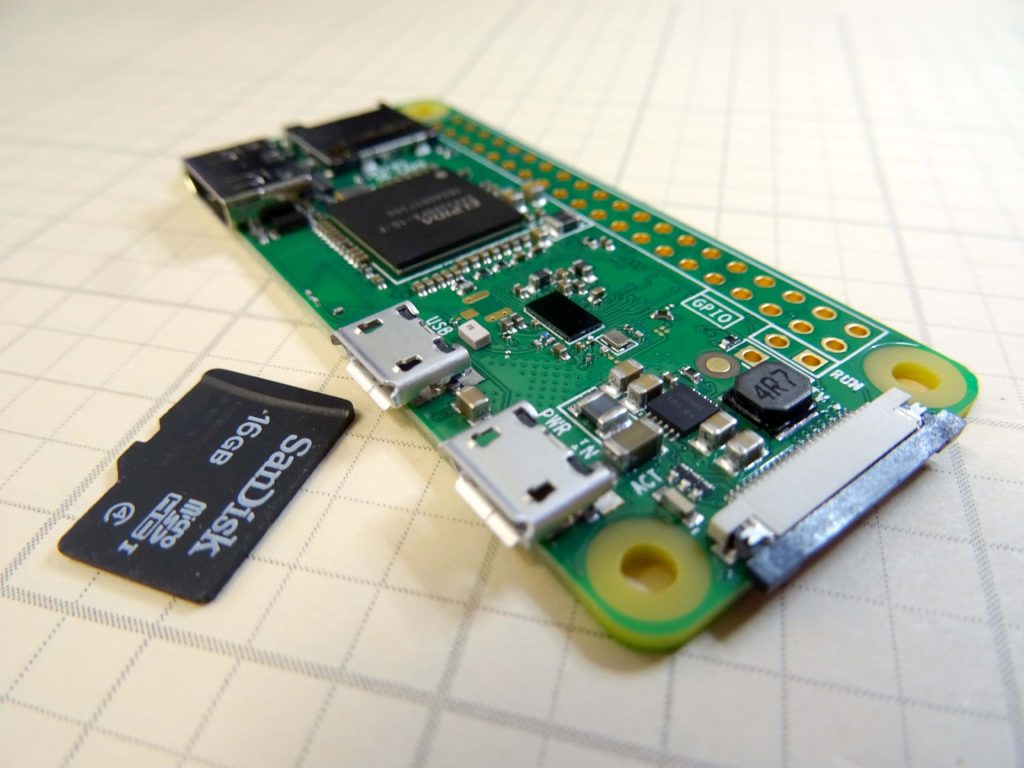
We have our Raspberry Pi Zero Model W booted up and running. Our interest is to run the device headless, but we must first discover our IP address. This lesson shows a simple tutorial on how to Boot the Pi Zero Model W, and get its IP address. Once you get the IP address, you will want to reserve that IP address for this device. You can do that through your wireless router, or if you are at work, talk to your Network Administrator. We plan to do a really cool project with this, so get your gear ordered now. The best deal we have found that has the two adapters you need can be ORDERED HERE.
This video takes you through setting up your Pi zero W step by step. Enjoy!
Low Cost Raspberry Pi IP Camera
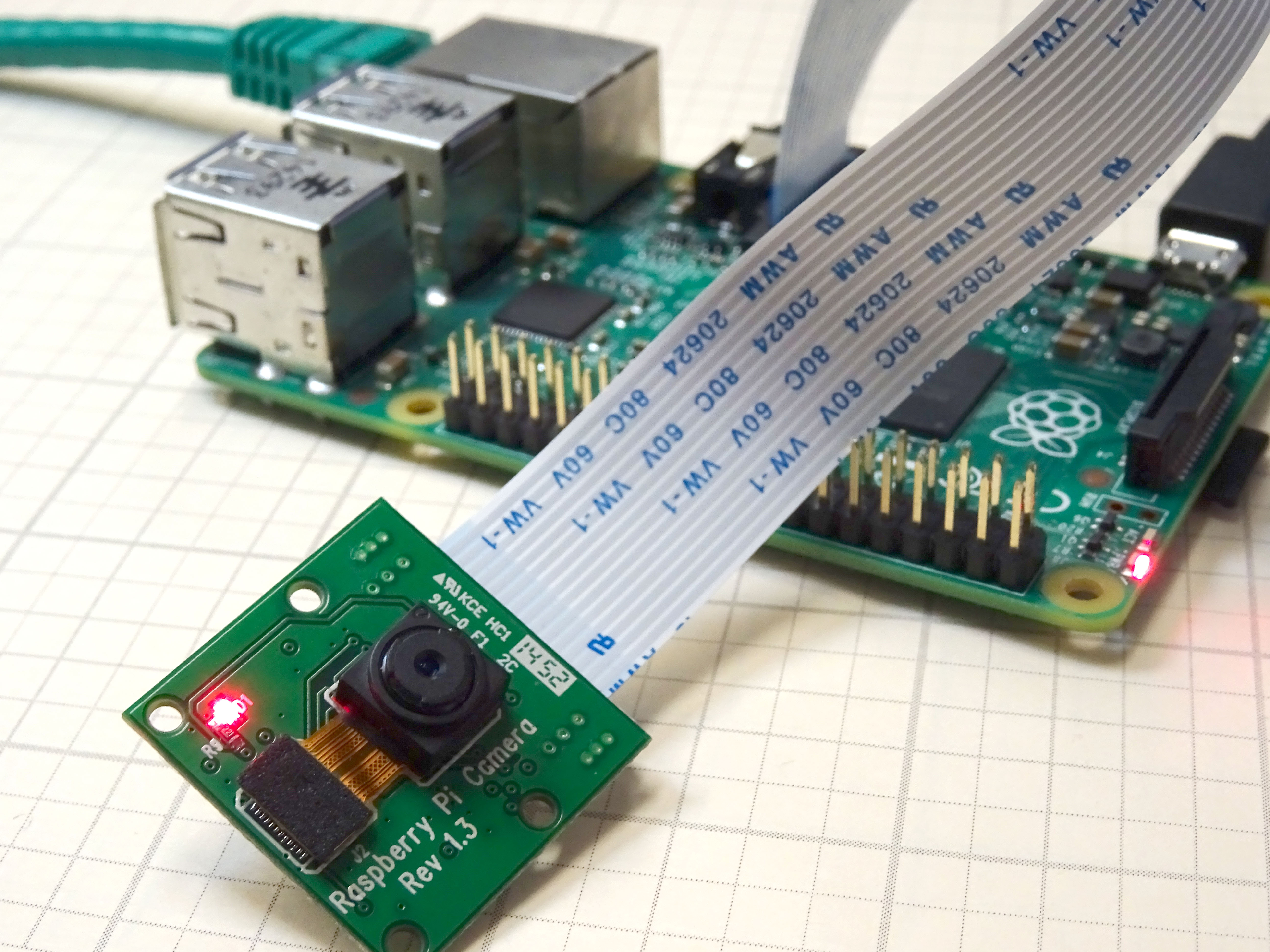
In this lesson we give you a step by step tutorial on how to create a low cost IP camera from a Raspberry Pi and the Raspberry Pi camera module. (If you need to get a Raspberry Pi and Camera Module, we recommend this complete starter Kit, which you can order HERE. If you already have a Raspberry Pi, and just need a camera, you can get the camera module HERE.) We are going to assume you already have your Raspberry Pi up and running, and are able to make a connection to it via Putty or SSH. If you are completely new to the Raspberry Pi, you should probably start with the first two lessons on THIS PAGE.
This video will take you through the steps one at a time. In addition, the tutorial below has the commands that you can copy and paste. We recommend you both follow the video, and get the steps from the instructions below, so you do not have to manually type the commands. Be very careful . . . you must be precise in following these instructions for things to work.
OK, now assuming you have your Raspberry Pi up and running, and you can connect via Putty or SSH, These are the steps to get your dandy personal IP camera working. You will type or copy and paste these lines one at a time into the Raspberry Pi command line.
STEP 1: Get Your Raspberry Pi Up to Date:
|
1 2 |
sudo apt-get update sudo apt-get upgrade |
STEP 2: Install Lighttpd Web Server:
|
1 |
sudo apt-get install lighttpd lighttpd-doc php5-common php5-cgi php5 zip |
STEP 3: Enable Server to Process PHP Scripts
|
1 2 3 |
sudo lighty-enable-mod fastcgi-php sudo lighty-enable-mod cgi sudo lighttpd-enable-mod fastcgi |
STEP 4: Create a PHP WEB Page:
|
1 |
sudo nano /var/www/html/php.php |
Now you will want to type or paste this info into the nano window.
|
1 |
<?php phpinfo(); ?> |
STEP 5: Save your nano file with these key strokes:
|
1 2 3 |
Ctrl O Enter Ctrl X |
To be clear, you press the Control key and the letter “O” at the same time. Then press the enter key. Then press the Control and “X” key at the same time.
STEP 6: Restart the Webserver:
|
1 |
sudo /etc/init.d/lighttpd restart |
STEP 7: Check That the WEB Server is Working:
Go to a browser on a Windows computer on your network, and type:
http://10.1.15.94/
(NOTE: You would use your Pi’s IP address above. The number I use above is the IP address of our Pi. Your number will be different. You can find out your IP address on the pi by typing ifconfig into the terminal window.)
If you configured things correctly, you should get an Apache info page pop up.
Also, you should be able to see your php information page by entering:
http:/10.1.15.94/php.php
Again, you should use your IP address. If you did things correctly you should have a page come up with lots of tables describing php configuration
STEP 8: Reboot Your Computer
|
1 |
sudo reboot |
STEP 9: Install the crtmpserver
|
1 |
sudo aptitude install crtmpserver |
STEP 10: Backup default crtmpserver file
|
1 |
sudo cp /etc/crtmpserver/applications/flvplayback.lua /etc/crtmpserver/applications/flvplayback.lua.bakORIGINAL |
STEP 11: Edit flvplayback.lua file
Open the file in nano editor:
|
1 |
sudo nano /etc/crtmpserver/applications/flvplayback.lua |
Now edit your file to these values:
|
1 2 3 4 |
validateHandshake=false, keyframeSeek=false, seekGranularity=0.1, clientSideBuffer=30, |
STEP 12: Save and Exit
|
1 2 3 |
Ctrl O Enter Ctrl X |
To be clear, you press the Control key and the letter “O” at the same time. Then press the enter key. Then press the Control and “X” key at the same time.
STEP 13: Restart crtmpserver
|
1 |
sudo /etc/init.d/crtmpserver restart |
STEP 14: Remove ffmpeg
We need to make sure we have a clean copy of ffmpeg, so safest thing to do is un-install it in case an old version is on your pi.
|
1 |
sudo aptitude remove ffmpeg |
STEP 15: Intall Latest git-core and ffmpeg software
|
1 |
sudo apt-get install git-core |
and then:
|
1 |
cd /usr/src |
and then:
|
1 |
sudo mkdir ffmpeg |
and then:
|
1 |
sudo chown `whoami`:users ffmpeg |
and then:
|
1 |
sudo git clone git://source.ffmpeg.org/ffmpeg.git ffmpeg |
and then:
|
1 |
cd ffmpeg |
and then:
|
1 |
sudo ./configure |
STEP 16: Now Make and Install the software:
These two commands will take a while. After inputting the commands go and get some coffee.
|
1 |
sudo make |
|
1 |
sudo make install |
STEP 17: Install Samba:
|
1 |
cd / |
We will want Samba to easily exchange files to and from windows.
|
1 |
sudo apt-get install samba samba-common-bin |
STEP 18: Edit Samba File:
|
1 |
cd /etc/samba |
|
1 |
sudo nano smb.conf |
Now you need to add these lines to the smb.conf file. You should add them into the SHARE DEFINITIONS section, after the netlogin part.
|
1 2 3 4 5 6 7 8 |
[home] path= / public= yes read only = no writeable = yes browseable = yes create mask = 0777 directory mask = 0777 |
After adding this code, my SHARE DEFINITIONS section looks like this:
|
1 2 3 4 5 6 7 8 9 10 11 12 13 14 15 16 17 18 19 20 21 22 23 24 25 26 27 28 29 30 31 32 33 34 35 36 37 38 39 40 41 42 43 44 45 46 47 48 49 50 51 52 53 54 55 |
#======================= Share Definitions ======================= [homes] comment = Home Directories browseable = no # By default, the home directories are exported read-only. Change the # next parameter to 'no' if you want to be able to write to them. read only = yes # File creation mask is set to 0700 for security reasons. If you want to # create files with group=rw permissions, set next parameter to 0775. create mask = 0700 # Directory creation mask is set to 0700 for security reasons. If you want to # create dirs. with group=rw permissions, set next parameter to 0775. directory mask = 0700 # By default, \\server\username shares can be connected to by anyone # with access to the samba server. # The following parameter makes sure that only "username" can connect # to \\server\username # This might need tweaking when using external authentication schemes valid users = %S # Un-comment the following and create the netlogon directory for Domain Logons # (you need to configure Samba to act as a domain controller too.) ;[netlogon] ; comment = Network Logon Service ; path = /home/samba/netlogon ; guest ok = yes ; read only = yes [home] path= / public= yes read only = no writeable = yes browseable = yes create mask = 0777 directory mask = 0777 # Un-comment the following and create the profiles directory to store # users profiles (see the "logon path" option above) # (you need to configure Samba to act as a domain controller too.) # The path below should be writable by all users so that their # profile directory may be created the first time they log on ;[profiles] ; comment = Users profiles ; path = /home/samba/profiles ; guest ok = no ; browseable = no ; create mask = 0600 ; directory mask = 0700 |
Now save and exit the nano editor with:
Ctrl O
Enter
Ctrl X
At this point, your Raspberry Pi should show up on your Windows computer network on your windows machine. On your windows machine, open a folder, click on “network” on the left, and you should see your raspberry pi show up. Now you can move files to and from your Raspberry Pi from Windows.
STEP 19: Install Strobe Software and WEB Page:
We will want to be able to view the live video stream in a browser, so we need to install the Strobe software. These next steps will install and enable the strobe feature.
|
1 |
cd /var/www/html |
|
1 |
sudo mkdir strobe |
|
1 |
sudo chmod -R 777 strobe |
Now the easiest way to get the strobe software is to download it on a windows computer. You can get the software by going to:
http://sourceforge.net/projects/smp.adobe/files/
and downloading the latest version of strobe media playback.
Now open the zipped folder and drag and drop the folder “for Flash Player 10.1” to your desktop.
Now move the CONTENTS of the unzipped “for Flash Player 10.1” folder onto your Raspberry Pi. You will want to move the CONTENTS of “for Flash Player 10.1” folder into the /home/var/www/html/strobe folder on your Raspberry Pi. If you installed Samba correctly, the Raspberry Pi should show up when you open a folder in Windows and click on “Network”.
Now you have the strobe software installed and you need to create a Strobe WEB page to display your live video.
First, make sure you are in the html folder by typing:
|
1 |
cd /var/www/html |
On your raspberry pi, now issue the command:
|
1 |
sudo nano index.html |
Now paste this code into your Nano window. You can paste by copying the code below, and then going to your Raspberry Pi command Window, and right mouse clicking.
|
1 2 3 4 5 6 7 8 9 10 11 12 13 14 15 16 17 18 19 20 21 22 23 24 25 26 27 28 29 30 31 32 33 34 35 36 37 38 39 40 41 42 43 |
<!DOCTYPE html PUBLIC "-//W3C//DTD XHTML 1.0 Strict//EN" "http://www.w3.org/TR/xhtml1/DTD/xhtml1-strict.dtd"> <html xmlns="http://www.w3.org/1999/xhtml"> <head> <title>My Spy PiCam</title> <script type="text/javascript" src="strobe/lib/swfobject.js"></script> <script type="text/javascript"> // Create a StrobeMediaPlayback configuration var parameters = { src: "rtmp://" + window.location.hostname + "/flvplayback/myStream", autoPlay: true, controlBarAutoHide: false, playButtonOverlay: true, showVideoInfoOverlayOnStartUp: false, optimizeBuffering : false, initialBufferTime : 0.1, expandedBufferTime : 0.1, minContinuousPlayback : 0.1, poster: "strobe/images/poster.png" }; // Embed the player SWF: swfobject.embedSWF ( "strobe/StrobeMediaPlayback.swf" , "strobeMediaPlayback" , 1080 , 720 , "10.1.0" , {} , parameters , { allowFullScreen: "true"} , { name: "strobeMediaPlayback" } ); </script> </head> <body> <div id="strobeMediaPlayback"> <p>Alternative content</p> </div> </body> </html> |
Now you should save and exit nano with these commands:
|
1 2 3 |
Ctrl O Enter Ctrl X |
To be clear, you press the Control key and the letter “O” at the same time. Then press the enter key. Then press the Control and “X” key at the same time.
STEP 20: Enable Raspbery Pi Camera Module:
At the command line enter:
|
1 |
sudo raspi-config |
Scroll down and enable the camera.
STEP 21: Start the Camera:
You are now ready to fire up the camera. You can start the camera by issuing this command in the Raspberry Pi command window.
|
1 |
raspivid -t -0 -w 1080 -h 720 -awb auto -fps 30 -rot 90 -b 1200000 -o - |ffmpeg -loglevel quiet -i - -vcodec copy -an -f flv -metadata streamName=myStream tcp://0.0.0.0:6666& |
STEP 22: View the Live Stream
Now to view the live stream just open a browser on a computer on your network and type in the IP address of your pi:
http://10.1.15.94
(Use your ip address. The one above is my IP address.
This has been a long project, but I hope well worth it. If you follow the instructions EXACTLY, it should work. Enjoy!
Beaglebone Black GPS LESSON 1: Hooking Up the Adafruit Ultimate GPS
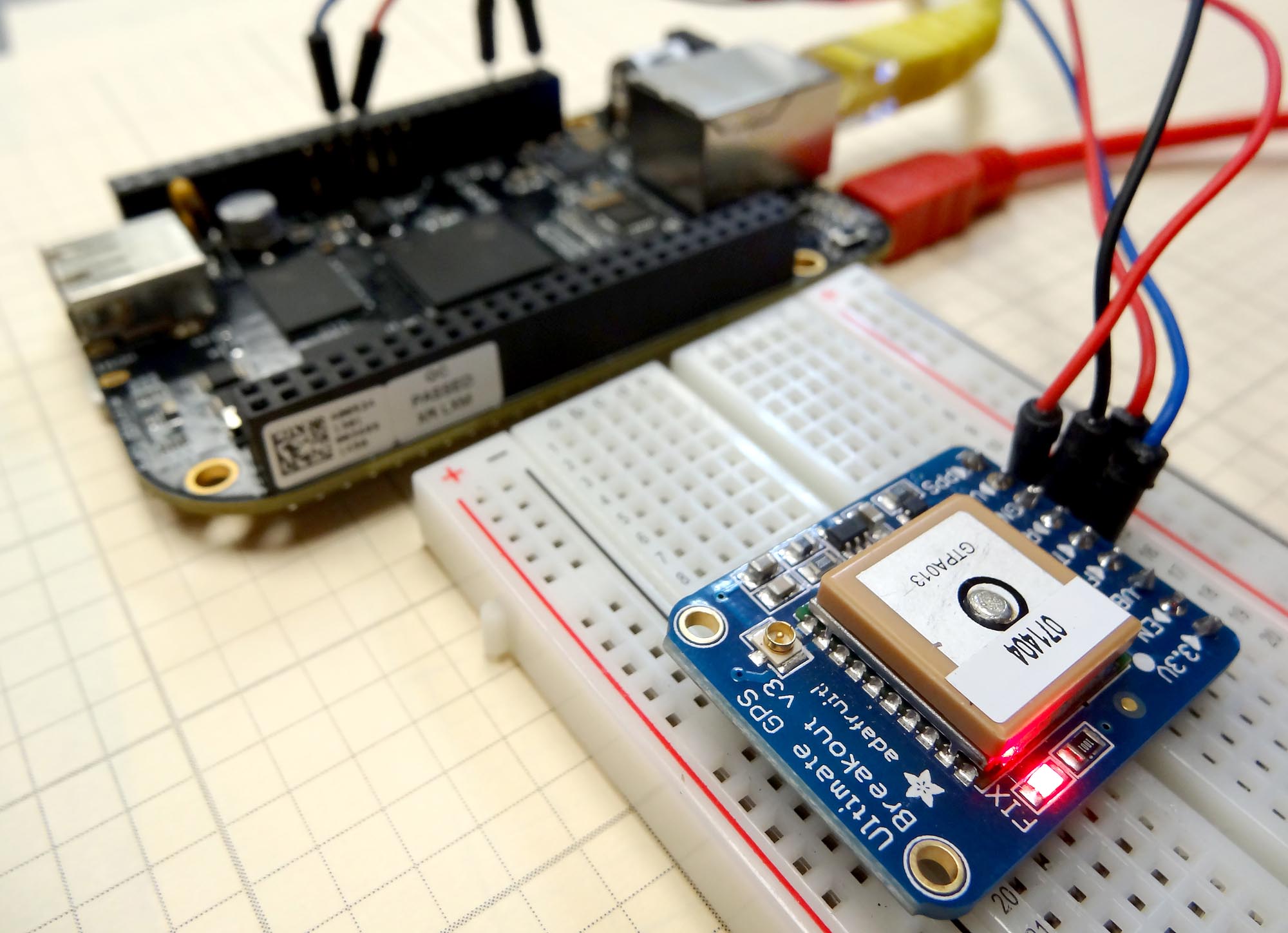
If you went through our series of 12 lessons on the Beaglebone black you should be familiar with the basics of this microcontroller. We are now ready to move on to more advanced projects. In our earlier lessons on the Arduino, we built a GPS data logger and integrated it with Google Earth using the Arduino Uno and the Adafruit Ultimate GPS Breakout Board. While that was a great project, we finally ran out of horsepower with the arduino, and what we could do was limited by the memory limitations on the Arduino. Also, it is very hard to parse strings in the Arduino IDE, so interpreting the NMEA sentences is a rather large challenge with the limited string functionality in Arduino.
Python on the other hand makes quick work of string manipulation and the Beaglebone Black has plenty of horsepower for any manipulation of the NMEA sentences we might want to do.
In order to play along with this project, you will need a Beaglebone Black Rev C, which you can get HERE, and the Adafruit Ultimate GPS which you can get HERE. The video below takes you through the project step-by-step, as well as the description below.
Once you get your gear, you will want to hook up the following circuit:

Note that we are working off header P9 and we are using P9_1 as ground, P9_7 as VIN, we are using P9_24 as Tx and P9_26 as Rx. Please note that you can see a detailed Diagram of the Beaglebone Black pinout HERE. Also notice that Tx on the Beaglebone is connected to Rx on the GPS, and Rx on the Beaglebone is connected to Tx on the GPS. Tx is like “talk” and Rx is like “listen, so you want to listen to the pin that is talking, and you want to talk to the pin that is listening.
Our goal in this first lesson is to establish a connection between the GPS and the Beaglebone, and to read in the data streaming from the GPS. We want to get a fix, and verify that we can read and print the NMEA sentences that contain the various position, altitude and velocity data.
The video takes you step-by-step through the code. The following simple code will get you streaming data from the GPS to your terminal window. In future lessons we will break the data down and show you how to get your position from the raw NMEA sentences streaming in.
|
1 2 3 4 5 6 7 8 9 |
import serial import Adafruit_BBIO.UART as UART UART.setup("UART1") GPS = serial.Serial('/dev/ttyO1', 9600) while(1): while GPS.inWaiting()==0: pass NMEA=GPS.readline() print NMEA |