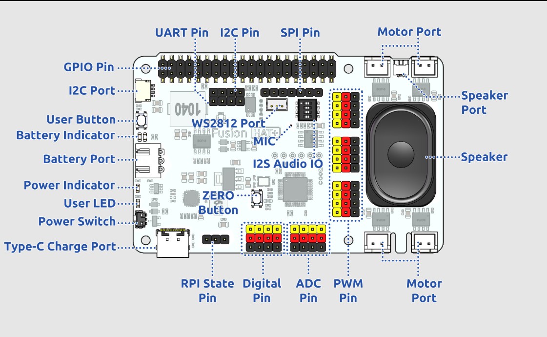
In today’s lesson we will become familiar with the capabilities of the Fusion AI Hat+ for the Raspberry Pi. This hat will be a core part of our class moving forward. The hat makes it easy to get data from the outside world, and to control things in the outside would. We will get an understanding of the core capabilities of the board, and your homework will be to build the first circuit with the board. This schematic shows the various parts of the board:
Fusion AI Hat for Raspberry Pi Schematic
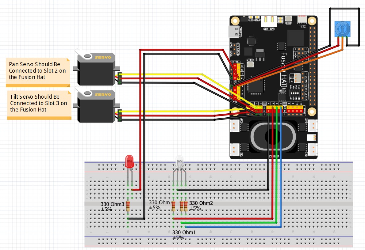
Then for the homework, we need you to go ahead and build this circuit. This circuit will allow us to learn how to make Digital Output commands, PWM commands, and how to read analog inputs.
This is the circuit we will use moving forward in the class
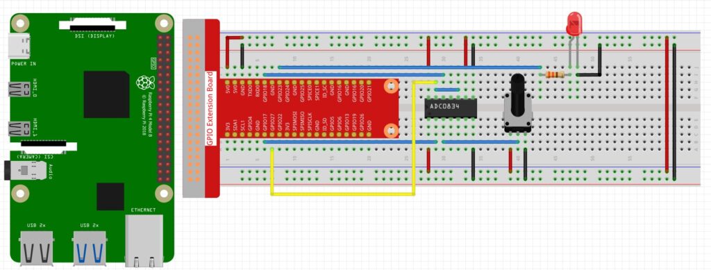
In this video lesson, we show how to create a dimmable LED on the raspberry pi using a potentiometer. Below is the schematic of the circuit we will be using.
Pot Controlled Dimmable LED
Then we used the following code to read values through the ADC0834 analog to digital chip, and then apply a PWM signal to control the brightness of the LED.
In this lesson we show how to configure the GPIO pins on the Jetson Nano to produce PWM signals. We show how the PWM libraries can be run in python. The Jetson Nano can provide Pulse Width Modulation signals on two physical pins, pins 32 and 33. We take you through the step by step process in the video above.
In Lesson 7, we learned how we can get in-between voltages from the Arduino pins using the analogWrite command. Actually, this command only approximates analog voltages, and does not produce actual analog signals. It works by quickly turning the voltage to the pin on and off. For example, if you ask for 2.5 volts, it will quickly switch the pin on, with it on 50% of the time and off 50% of the time. Similarly, if you asked for 1 volt, it is really switching 5 volts on and off quickly. For this case, it would be on 20% of the time and off 80% of the time. This technique is called Pulse Width Modulation. In this video we show you the actual waveforms coming from the analogWrite command on an oscilloscope. If you want to follow this lesson at home, an official Arduino Uno R3 is available HERE. In this new series of lessons, I will be using the sensor and other components found in this KIT.
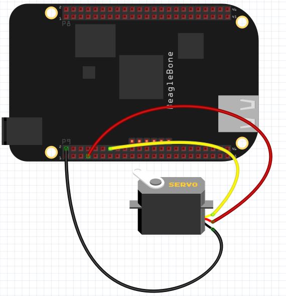
This lesson will show how to use Python running on the Beaglebone Black to control the position of a servo. First, I am using a small servo that I have verified can be powered from the Beaglebone Black without drawing too much current. All servos are different, so if you are unsure of the current requirements of your servo, it is safest to power it from an external 5 Volt power source. You can still control it through the control line connected to the Beaglebone Black, just make sure the servo and Beaglebone have a common ground.
Control of Servo From Beaglebone Black.
Most all servos have three wires; Power, Control, and Ground. For my servo, Control is Yellow, Power is Red, and Ground is Black. If you have a different servo, check the data sheet to see what colors are Control, Power and Ground on your servo. Note we are using pin P9_2 as ground, P9_7 as 5V power, and P9_14 as our control pin.
We will be controlling the position of the servo using PWM. We will have to play around with our individual servo to determine precisely what signal pulse width will result in the servo being in the full left position, and what pulse width will result in the servo being in the full right position.
For most servos, full left is somewhere around 1 milliseconds, and the pulse width that will give us full right position is about 2 milliseconds. These are ballpark numbers, and we will have to play around with things to find the exact values for our servo.
We will set up a 50 Hz PWM signal. A 50 Hz signal has a period of:
period = 1/frequency = .02 seconds = 20 miliseconds.
Hence, if we want to get to about the full left position we would want a duty cycle of about 5%. Because 20 milliseconds x .05 = 1 milliseconds. This one millisecond pulse width should put the servo about in the full left position. Similarly for the full right position, we would want a duty cycle of 10%, because that would give us a pulse width of 2 milliseconds, since:
PulseWidth = Period x DutyCycle
PulseWidth = 20 x .1 = 2 milliseconds.
We can use the following code to determine precisely for our servo what dutyCycle will give the precise full left and full right positions.
Python
1
2
3
4
5
6
importAdafruit_BBIO.PWM asPWM
servoPin="P9_14"
PWM.start(servoPin,5,50)
while(1):
dutyCycle=input("What Duty Cycle? ")
PWM.set_duty_cycle(servoPin,dutyCycle)
For my servo, running a 50 Hz PWM singnal, I find that a duty cycle of 2% puts it in the full left position and a duty cycle of 12% puts it in the full right position.
Now we would like to be able to just specify an angle we want and have it go to that angle. If we want an angle of 0 degrees we would apply a 2% duty cycle. This value is for my servo. You will have to play around with your servo and the code above to find what this number is for you. But for me, I have the point:
(0,2)
That is to say when I desire an angle of 0 on the servo, I should apply a dutyCycle of 2 to the PWM pin. Similarly, when I desire 180 degrees, I should apply a dutyCycle of 12. (Again, this number might vary for your servo). For my servo, I get the point:
(180, 12)
We can fit a line to these points, which would then allow us to calculate the dutyCycle for any desired angle. The slope from the two points above would be:
m=(y2-y1)/(x2-x1)=(12-2)/(180-0) = 10/180= 1/18
Using the point slope form of the line, we would get
y-y1 = m (x- x1)
y – 2 = 1/18( x – 0)
y= 1/18*x + 2
Now putting in our actual variable names we get:
dutyCycle = 1/18*desiredAngle + 2
You can develop the same type equation just using the values suitable for your servo from the experiment above.
Now we can use this code to smoothly move the servo to any desired position.
Python
1
2
3
4
5
6
7
importAdafruit_BBIO.PWM asPWM
servoPin="P9_14"
PWM.start(servoPin,2,50)
while(1):
desiredAngle=input("What Angle do You Want")
dutyCycle=1./18.*desiredAngle+2
PWM.set_duty_cycle(servoPin,dutyCycle)
Making The World a Better Place One High Tech Project at a Time. Enjoy!
We use cookies to ensure that we give you the best experience on our website. If you continue to use this site we will assume that you are happy with it.