Tag Archives: Python

Raspberry Pi LESSON 27: Analog Voltages Using GPIO PWM in Python

If you remember our Arduino Lessons, you will recall that we could write analog voltages to the output pins with the ~ beside them. The truth is, though, we were not really writing analog voltages, we were just simulating analog voltages using pulse width modulation (PWM). The arduino was able to put out 5 volts. Hence, if you want to simulate a 2.5 volt signal, you could turn the pin on and off every quickly, timing things such that the pin was on half the time and off half the time. Similarly, if you wanted to simulate a 1 volt analog out, you would time things so that the 5 volt signal was on 20% of the time. For many applications, such as controlling LED brightness, this approach works very well. Arduino made it easy and transparent to the user to generate these analog-like output voltages using the analogWrite command.

This capability is also available on the Raspberry Pi GPIO pins. However, the implementation requires you to think in terms of a signal with a frequency and a duty cycle. Consider a signal with a frequency of 100 Hz. This signal would have a Period of 10 milliseconds. In other words. the signal repeats itself every 10 milliseconds. If the signal had a duty cycle of 100%, it would be “High” 100% of the time, and “Low” 0% of the time. If it had a duty cycle of 50% it would be high 50% of the time (.5X10 milliseconds= 5 milliseconds) and low 50% of the time (.5X10 milliseconds = 5 milliseconds). So, it would be high 5 milliseconds, and low 5 milliseconds for a total period of 10 milliseconds, which as we expect, if a frequency of 100 Hz. (Note that the Period of a signal = 1/frequency, and frequency = 1/Period)

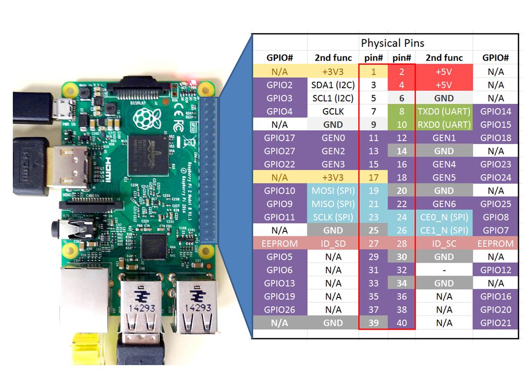
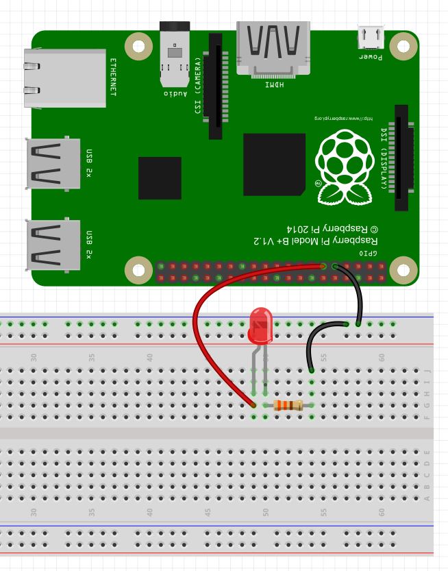
Note on the Raspberry Pi, the output voltage is 3.3 volts as opposed to the 5 volt output on the Arduino. Hence, the Raspberry Pi can only simulate analog voltages between 0 and 3.3 volts. For this example, we will be playing with the following circuit again. Note we are using physical pin 9 as the ground and physical pin 11 as the power pin. See Lesson 25 below for a diagram of pin numbers on the Raspberry Pi.

Raspberry Pi Circuit
This Circuit Will Blink a Red LED

OK, enough background, lets start playing with some code. On examples like this, I think it is easiest to operate from the Python Shell, as this allows us to observe the effects of our commands one at a time. To enter the Python Shell, type sudo python at the linux command line in a terminal window. The sudo is important as it allows you to enter the python shell as a superuser. Access to the GPIO pins requires superuser privileges. Also, remember that to exit the python shell and return to the Linux command prompt you enter Ctrl-d. So, type in sudo python to go to the python shell. You should see the >>> prompt indicating you are not in the python shell. The first thing you need to do is import the RPi library:

>>> import RPi.GPIO as GPIO

Now tell the Raspberry Pi which pin number scheme you want to use (See Lesson 25).  I prefer to use the physical pin numbering system as I find it easier to remember. To use the physical pen numbering system, you would enter this command:

>>> GPIO.setmode(GPIO.BOARD)

Note, if you prefer the BCM system, replace BOARD with BCM in the command above.

Now we need to tell the Pi that physical pin 11 will be an output. We can do that will the command:

>>> GPIO.setup(11,GPIO.OUT)

At this point we could write the pin high or low, but our objective here is to use PWM, so we need to do a few more things. First, we need to create a PWM object. I will call my object my_pwm. We will need to pass the parameters of the physical pin we want to use, and the frequency. I like to use 100 Hz, which gives us a period of 10 msec. The command we need for this is:

>>>my_pwm=GPIO.PWM(11,100)

Remember capitalization needs to be EXACT! Now to start the pwm we need to decide what DutyCyle we want. Remember, the DutyCycle is the percentage of the period that the signal will be high. If we wanted to approximate a 1.6 volt signal, we would note that 1.6 is about half of the 3.3 coming out of the Pi, so we would want a 50% duty cycle. The command for this would be:

>>>my_pwm.start(50)

When you type this command you should see the LED come on, if you have connected things correctly. It should be at about half brightness.

Now if you would like to change the brightness, just change the Duty Cycle. For example, if you wanted the LED very dim, you might set a 1% duty cycle. You could do this with the command:

>>>my_pwm.ChangeDutyCycle(1)

Similarly, if you wanted full brightness, you would want a 100% duty cycle, which you could get with the command:

>>>my_pwm.ChangeDutyCycle(100)

Again, please remember that the capitalization has to be exact. Now you can get any brightness you want by changing the duty cycle to anything between 0 and 100, inclusive.

Note you can also change the frequency of the PWM signal. Lets say you wanted a frequency of 1000 Hz. We could do this with the command:

>>>my_pwm.ChangeFrequency(1000)

Note that by doing this there is no perceptible change in LED brightness because you have not changed the relative on and off time of the signal. You are just going faster, but not impacting the fractional time the signal is on and off, hence the LED brightness does not change.

While in these examples we have done things from the control line, you can write python programs that will run the commands for you. For example, write a program that asks the user how bright he wants the LED, between 0 and 100, and then set it to that brightness by adjusting the Duty Cycle, as we did in the example above. Play around with different pins and different frequencies and values. Become familiar with these commands.

Now, finally, if you want to turn pwm off, you would use the command:

>>>my_pwm.stop()

Also, remember that you should always clean up after yourself, so at the bottom of your program, or before you exit the shell, always release your pins and clean up using the command:

>>>GPIO.cleanup()

Raspberry Pi LInux LESSON 26: Controlling GPIO Pins in Python

In this lesson we will actually begin to control the GPIO pins from the Raspberry Pi. We will start by looking at how to write a pin high or low. We will be doing this in the Python programming language. A really important thing to remember is that the default “Pi” user does not have access to the pins, so for these examples to work, you must run the programs with “sudo”. The sudo command executes as super user, and will give the program access to the GPIO pins.

To begin with, lets build a simple circuit. If you purchased the kit we showed in lesson 1, you should have all the components you need to follow along with these examples. If you have not purchased a kit yet, you can get one on amazon.com HERE.  In this first lesson we will just be looking at blinking an LED. So, you can now go ahead and hook up the following circuit. For reference, we show below the pinout of the Raspberry Pi.

Raspberry Pi 2 Pinout
This figure shows the Raspberry Pi GPIO pinout

In this example we will be using physical pin 9 as a ground, and physical pin 11 as the control pin. You can now go ahead and hook up the following circuit. Please remember the direction you plug the LED in matters . . . the long leg needs to connect to pin 11. The resistor used should be about 330 ohms.

Raspberry Pi Circuit
This Circuit Will Blink a Red LED

In order to become familiar with the commands, I like to start in the Python shell. Basically, we give the commands to python one line at a time and watch what happens. Then later, we can write and run programs.

Note that recent versions of the Raspberry Pi distribution include the RPi library, but if you have an older distribution, update your system using these commands:

$ sudo apt-get update

and

$ sudo apt-get upgrade

If you have not done this is a while, it can take some time to download and install the updates.

We are now ready to begin to work with the GPIO pins. To enter the python shell, open a terminal window on the Raspberry Pi, and you will want to type:

$ sudo python

Be sure and use the sudo command above, as that will give you administrative access to the GPIO pins. Now, you should get the python command shell prompt, that looks like this:

>>>

At this point, any command you type will be executed by the python interpreter. You can basically execute a python program one line at a time. Note, to exit the python shell type Ctrl-d.

OK, so lets see if we can control the LED!

First, we need to import the RPi library. Note this is case sensitive, so be careful to do capitalization exactly:

>>> import RPi.GPIO as GPIO

Now, we need to initialize the GPIO to use either the BOARD or the BCM pin numbering schemes. In the diagram at the top of this lesson, the BOARD numbering convention is shown in the center two columns. If you want to use the BCM numbering scheme, you would use the numbers indicated in the outer two columns. In these examples, I want to use the physical pin numbers, as that is easier to me to keep track of things. Hence, I will want to use the BOARD scheme. I can do that with this command:

>>>GPIO.setmode(GPIO.BOARD)

As you can imagine, if you want to use BCM, BOARD should be replaced with BCM in the command above.

If you remember in our Arduino lessons, we had to do pinmode commands to tell the arduino whether pins are inputs or outputs. We do an analogous thing in Raspberry Pi. We need to tell the Pi whether we will be using a pin as an input or output. In the wiring diagram above, you can see that we want to power the LED from physical pin 11, so we need to set that as an output.

>>>GPIO.setup(11,GPIO.OUT)

We are now ready to turn the LED on. We can do this by setting pin 11 to True:

>>>GPIO.output(11,True)

Now to turn the LED off, we can do:

>>>GPIO.output(11,False)

You can now play around with different GPIO pins, and turn the LED on and off as you like. Before leaving the Python shell, be sure to clean up the GPIO. You do this by giving the cleanup command:

>>>GPIO.cleanup()

This will ensure you do not get error messages if you try to work with the GPIO pins again. It is a good practice to always cleanup after you are done.

Python with Arduino LESSON 17: Sending and Receiving Data Over Ethernet

Arduino Ethernet
This circuit contains an Arduino Nano and Pressure Sensor Communicating over Ethernet

In LESSON 16 we showed a simple Client Server model that allows us to send strings between Python running on a PC and the arduino over Ethernet. That lesson simply passed strings back and forth to show a very basic Server on Arduino, and Python acting as the Client. In this lesson we show a more practical example, with the Arduino connected to an Adafruit BMP180 Pressure Sensor. In order to complete this lesson, you will need an Arduino, an Ethernet Shield, and the Pressure Sensor. If you do not have this particular pressure sensor, you can probably follow along in the lesson using whatever sensor you have that is of interest. The video will take you through the tutorial step-by-step, and then the code we developed is shown below.

The key issue in getting this project to work is to get your mac address and IP address from your router or network. If you are at school, simply speak to your network administrator, and he will help you get an IP address for your arduino. If you are at home, you will need to connect to your router from a browser, and configure it to assign an IP address and agree on a mac address for your arduino. Some arduino Ethernet shields have a sticker with a mac address. If your Ethernet shield has a sticker with mac address, use that one. If it does not, you will need to come up with a unique mac address. There are thousands of possible routers and networks out there, so I can not help you with that part. But if you look in the router documentation, you should be able to get the IP address and mac address worked out. The arduino itself does not have a hard wired mac address, but you set the mac address in the arduino software, and the IP address as well. The key thing is that the mac address is unique on your network, and the router and arduino agree on the IP address and mac address. If you have a clearer way to explain this, please leave a comment below.

This is the server side software to run on the arduino. Again, you should use a suitable IP address and mac address for your network. Do not think you can just copy the ones I use in the code below.

Once you have this on your arduino, and the arduino connected to the internet via an Ethernet cable, you can test by opening a command line in Windows. Then ping the address you have assigned to the Arduino. If it pings correctly and you get a reply, you are ready to develop the Python code. The Python will be the client. It will send the requests to the Arduino, and the Arduino will respond with data. Since our circuit can measure pressure or temperature, you can request either of those. When the arduino receives a request for temperature, it will go out, make the temperature measurement and then return the data to Python. Similarly, if you request Pressure the arduino will read the request, will make the Pressure measurement, and then return pressure reading to the client (Python).

 This python code will request Temperature, will then read the response, and then will print the data. It then requests Pressure, reads the response, and then prints it. If you look at our earlier lessons you can see graphical techniques to visually present the data. The hard part is getting the data passed back and forth, which we show how to do in this lesson.

Python with Arduino LESSON 16: Simple Client Server Configuration over Ethernet

Arduino and Ethernet Shield
Ethernet Shields are available which allow the arduino to act as a server

In the previous lessons we have seen that powerful analytic and graphic programs can be written that allow data taken from the arduino to be displayed on a PC via Python. We have shown how the arduino can be connected to a PC by either a serial cable or Xbee radios. To fully unleash the power of the arduino, it can be set up as a server, and connected to a network via Ethernet. In this lesson, we will show how to set the arduino up as a server which is controlled and queried by clients on PC’s on the same network. In order to complete this tutorial, you will need an Arduino Uno and an Ethernet shield. The Ethernet Shield is a relatively expensive component, but I suggest getting an authentic arduino made shield, as I have had poor results from the cheap knock offs. Understand that this lesson is intended for High School students to show them a simple technique for connecting the arduino to a network. It is not an exhaustive treatise on Ethernet communication. The goal is to provide a simple protocol which should allow you to get your arduino talking over Ethernet. It requires that you already know, or can figure out how to assign a mac address and IP address in your router. Some arduino Ethernet shields have a sticker with a mac address. If your Ethernet shield has a sticker with mac address, use that one. If it does not, you will need to come up with a unique mac address. If you are at school, the network administrator can help you get the router configured. I can not provide support in getting this to work on your network, as there are many variables. The techniques provided in this tutorial should work for most networks. This tutorial does not present the most efficient or elegant solution, but the goal is a simple protocol for people just getting started. The video below gives a step-by-step demonstration of setting up the arduino as a server, and Python on a PC as the client. It uses UDP protocol to transfer data packets.

In order to get the arduino to work over Ethernet, you must first assign an IP address to the arduino in your router.  If you just plug the arduino with shield into the network, your router might assign an IP and report a mac address. If this is the case, you need to have the router assign those addresses permanently to the arduino. The bottom line is that the IP address and mac address you identify in the arduino code must match the IP address and mac address assigned in the router. I can not provide any additional help on that issue as there are so many different possible networks. You have to figure out how to do that.

Once you have the IP address and mac address sorted out, you will need to set up the arduino as a server. The video above explains how to do this, and results in this code. Note that your IP address and mac address must be set to a suitable configuration for your router and network. The numbers I use in this code would not work for your network.

This is the code developed in the video to set the arduino up:

Once you have this code in your arduino, ping the IP address of the arduino from your PC cmd line. Make sure your PC can talk to the arduino by successfully pinging it. If you get an error while you are trying to ping the arduino, you will have to stop and get figured out what is wrong. There is no reason to proceed with the lesson until you can successfully ping the arduino.

Once you can ping the arduino, you are ready to set up a client in Python. The code below is what we developed in the video. You will need to watch the video in order to understand the code. Also note, that the IP address in the code below is the IP address of the Arduino, NOT the PC. You should set this to whatever IP address is of YOUR arduino.

 Again, this is a bit of a tricky thing to set up, but if you get the PC successfully pinging the arduino, everything else should be straightforward.