In this series of lessons, we will be controlling the GPIO pins from Python. If you do not already have a Beaglebone Black Rev. C, you can pick one up HERE.
In this lesson we show you how to write and run a simple Python program. Be sure to go through LESSON 2, which shows you how to boot and remotely connect to the Beaglebone. You will need to know how to do that for this lesson.
In this lesson we show you how to boot up your Beaglebone Black, and how to connect via the Putty SSH terminal client, and how to remotely run the graphical desktop on your PC. If you do not already have your Beaglebone Black, you can pick up one HERE.
The Beaglebone black has only one USB connection, so I find the easiest way to work with it is to just connect by a remote desktop, instead of trying to connect screen, keyboard, and mouse directly to the Beaglebone. This lesson will get you started so you can get connected and talking to your Beaglebone.
In this lesson we are ready to bring together a lot of what we learned in earlier lessons. We will create dimable LEDs which will respond to two buttons. If one is pressed the LED will gradually grow dimmer. If the other is pressed, the LED will gradually grow brighter. This will require us to use our skills in using GPIO inputs, pullup resistors, GPIO outputs, and PWM.
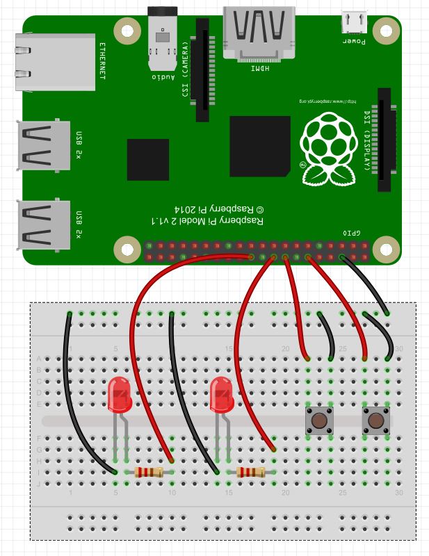
For convenience we will use the same circuit we used in LESSON 30, shown below. Also, if you want to follow along with these lessons, you can buy the gear you need HERE.
This Circuit Controls two LED from Push Buttons Using the Raspberry Pi
The objective of this circuit is that we want the LEDs to grow brighter each time the right button is pushed, and we want them to grow dimmer each time to left button is pushed.
The video above steps through and explains this code.
Python
1
2
3
4
5
6
7
8
9
10
11
12
13
14
15
16
17
18
19
20
21
22
23
24
25
26
27
28
29
30
31
32
33
34
fromtimeimportsleep# Library will let us put in delays
importRPi.GPIO asGPIO# Import the RPi Library for GPIO pin control
GPIO.setmode(GPIO.BOARD)# We want to use the physical pin number scheme
button1=16# Give intuitive names to our pins
button2=12
LED1=22
LED2=18
GPIO.setup(button1,GPIO.IN,pull_up_down=GPIO.PUD_UP)# Button 1 is an input, and activate pullup resisrot
GPIO.setup(button2,GPIO.IN,pull_up_down=GPIO.PUD_UP)# Button 2 is an input, and activate pullup resistor
GPIO.setup(LED1,GPIO.OUT)# LED1 will be an output pin
GPIO.setup(LED2,GPIO.OUT)# LED2 will be an output pin
pwm1=GPIO.PWM(LED1,1000)# We need to activate PWM on LED1 so we can dim, use 1000 Hz
pwm2=GPIO.PWM(LED2,1000)# We need to activate PWM on LED2 so we can dim, use 1000 Hz
pwm1.start(0)# Start PWM at 0% duty cycle (off)
pwm2.start(0)# Start PWM at 0% duty cycle (off)
bright=1# Set initial brightness to 1%
while(1):# Loop Forever
ifGPIO.input(button1)==0:#If left button is pressed
print"Button 1 was Pressed"# Notify User
bright=bright/2.# Set brightness to half
pwm1.ChangeDutyCycle(bright)# Apply new brightness
pwm2.ChangeDutyCycle(bright)# Apply new brightness
sleep(.25)# Briefly Pause
print"New Brightness is: ",bright# Notify User of Brightness
ifGPIO.input(button2)==0:# If button 2 is pressed
print"Button 2 was Pressed"# Notify User
bright=bright*2# Double Brightness
ifbright>100:# Keep Brightness at or below 100%
bright=100
print"You are at Full Bright"
pwm1.ChangeDutyCycle(bright)# Apply new brightness
pwm2.ChangeDutyCycle(bright)# Apply new brightness
sleep(.25)# Pause
print"New Brightness is: ",bright#Notify User of Brightness
In this lesson we will show how you can control LED’s from push buttons. In order to get started, you will want to expand the circuit we built in LESSON 29 to include two LEDs. The schematic below shows how you will want to hook things up (Also, remember you can see the Raspberry Pi pinout in LESSON 25). Also, as we have mentioned before, if you want to follow along with us in these lessons you can get a kit that has all the gear you need HERE.
This Circuit Controls two LED from Push Buttons Using the Raspberry Pi
In the video lesson, we take you through the code step-by-step. We use the techniques learned in LESSON 29 to detect if a button has been pushed. We introduce two new variables, BS1 and BS2, so indicate the state of the LED’s. A BS1=False means the LED1 is off. A BS1=True means the LED is on. This concept allows us to determine whether we should turn the LED on or off when the button is pushed. Basically, we want to put it in the opposite state when a button is pushed. The code is below. The video shows how it works.
Python
1
2
3
4
5
6
7
8
9
10
11
12
13
14
15
16
17
18
19
20
21
22
23
24
25
26
27
28
29
30
31
32
33
34
fromtimeimportsleep# Import sleep Library
importRPi.GPIO asGPIO# Import GPIO Library
GPIO.setmode(GPIO.BOARD)# Use Physical Pin Numbering Scheme
button1=16# Button 1 is connected to physical pin 16
button2=12# Button 2 is connected to physical pin 12
LED1=22# LED 1 is connected to physical pin 22
LED2=18# LED 2 is connected to physical pin 18
GPIO.setup(button1,GPIO.IN,pull_up_down=GPIO.PUD_UP)# Make button1 an input, Activate Pull UP Resistor
GPIO.setup(button2,GPIO.IN,pull_up_down=GPIO.PUD_UP)# Make button 2 an input, Activate Pull Up Resistor
GPIO.setup(LED1,GPIO.OUT,)# Make LED 1 an Output
GPIO.setup(LED2,GPIO.OUT)# Make LED 2 an Output
BS1=False# Set Flag BS1 to indicate LED is initially off
BS2=False# Set Flag BS2 to indicate LED is initially off
while(1):# Create an infinite Loop
ifGPIO.input(button1)==0:# Look for button 1 press
print"Button 1 Was Pressed:"
ifBS1==False:# If the LED is off
GPIO.output(LED1,True)# turn it on
BS1=True# Set Flag to show LED1 is now On
sleep(.5)# Delay
else:# If the LED is on
GPIO.output(LED1,False)# Turn LED off
BS1=False# Set Flag to show LED1 is now Off
sleep(.5)
ifGPIO.input(button2)==0:#Repeat above for LED 2 and button 2
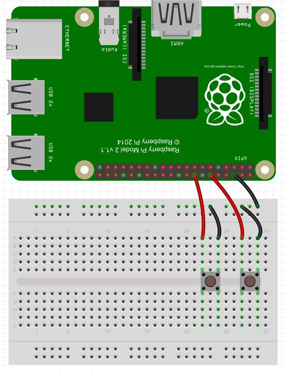
We are now ready to learn how to “read” values from the Raspberry Pi GPIO pins. In order to demonstrate this, we will show a simple example using buttons. If you ordered the Raspberry Pi kit we recommend, you already have everything you need, or you can pick your kit up HERE. To start with, you need to put together a simple circuit that connects two push buttons to your Raspberry Pi. Connect according to this schematic.
Simple Circuit Connecting Two Push Buttons to the Raspberry Pi
Note that one leg of each button is connected to the ground rail on the breadboard, that is connected to the Pi ground at physical pin 6. Then we connect the left leg of the left button to physical pin 16, and the left leg of the right button to physical pin 12.
In order to read the state of these buttons, that is, whether they are being pressed or not, we need to write a python program. To begin with we must import GPIO library and specify that we want to
Python
1
2
3
fromtimeimportsleep# Import time library
importRPi.GPIO asGPIO# Import RPi Library
GPIO.setmode(GPIO.BOARD)# Specify We Want to reference Physical pins
Now we are ready to set the pin modes on the pins we are using. We are using pins 12 and 16. We will set up variables so that we can reference the pins by descriptive variables.
Python
1
2
3
4
button1=16# Descriptive Variable for pin 16
button2=12# Descriptive Variable for pin 12
GPIO.setup(button1,GPIO.IN,pull_up_down=GPIO.PUD_UP)# Set button1 as input and Activate pull up resistor
GPIO.setup(button2,GPIO.IN,pull_up_down=GPIO.PUD_UP)# Set button2 as input and Activate pull up resisor
Note in our GPIO.setup commands, we are not just defining the pins as inputs, we are also activating pullup resistors with
Python
1
pull_up_down=GPIO.PUD_UP
With this command, the raspberry pi places a pullup resistor between the designated pin and the 3.3 V rail. This means that if we simply read the pin, we will read a “1”, “True”, or “High”, since the pin will see the rail through the pullup resistor. If we connect the pin to ground by pressing a button or switch, the pin will then read a “0”, “False” or “Low” because it will be a straight connection to ground, and as current flows through the pullup resistor, the 3.3 Volts will drop across the pullup resistor. Hence, the pin sees 0 volts.
The result is that with the pullup resistor activated, the pin will always report a “1” until something connects the pin to ground, and then it will read a “0”. This configuration should work for most things, but if you are getting unpredictable results which can result from electrical noise, then try using external pullup resistors.
Now we are ready to read the values from the pins.
Arduino
1
2
3
4
5
6
7
8
while(1):# Create an infinite loop
ifGPIO.input(button1)==0:# button1 will report 0 if it is pressed
print"Button 1 Pressed"
sleep(.1)# delay
ifGPIO.input(button2)==0:# button 2 will report 0 if it is presses
sleep(.1)
print"Button 2 Pressed"
Notice that we read from the pin using the GPIO.input command. Also note that for reliable results you need to usually put a small delay in your code. This will help debounce the button, and will also give more stable results.
This code will sit and monitor the buttons, and when one is pressed it will report that that button has been pressed.
Making The World a Better Place One High Tech Project at a Time. Enjoy!
We use cookies to ensure that we give you the best experience on our website. If you continue to use this site we will assume that you are happy with it.