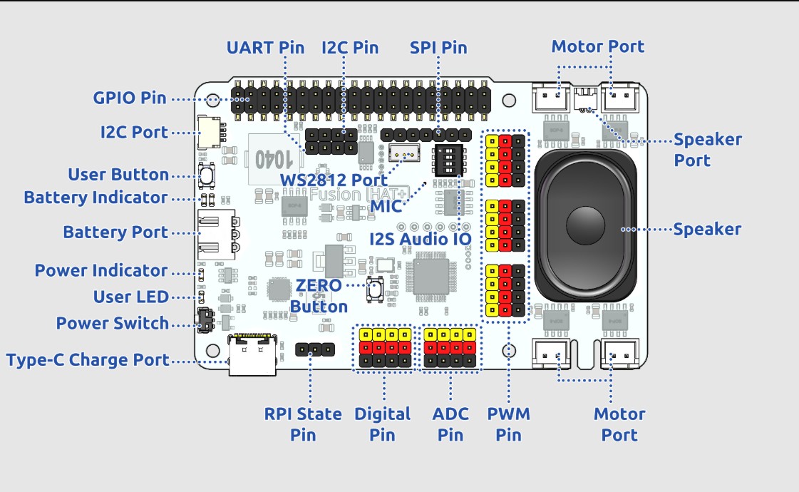
In today’s lesson we will become familiar with the capabilities of the Fusion AI Hat+ for the Raspberry Pi. This hat will be a core part of our class moving forward. The hat makes it easy to get data from the outside world, and to control things in the outside would. We will get an understanding of the core capabilities of the board, and your homework will be to build the first circuit with the board. This schematic shows the various parts of the board:
Fusion AI Hat for Raspberry Pi Schematic
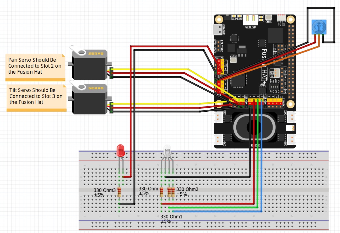
Then for the homework, we need you to go ahead and build this circuit. This circuit will allow us to learn how to make Digital Output commands, PWM commands, and how to read analog inputs.
This is the circuit we will use moving forward in the class
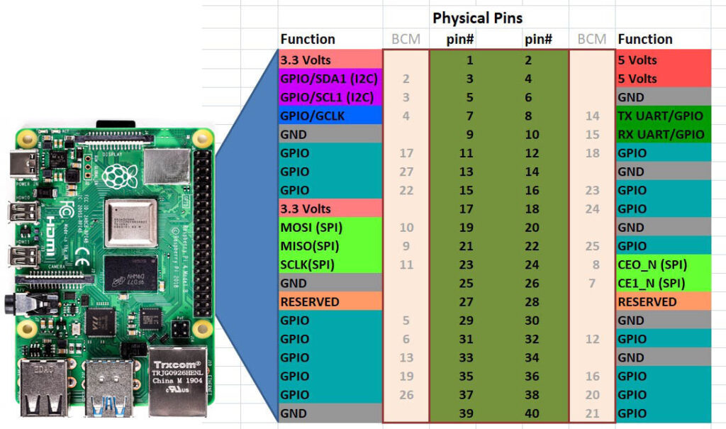
This shows the pinout for the Raspberry Pi 4. It shows both the BOARD numbering scheme, and the BCM numbering scheme. You define which numbering scheme you want to use in your python program. You must start by importing the GPIO Library:
import RPi.GPIO as GPIO
Then, if you use setmode to define which numbering scheme you want:
GPIO.setmode(GPIO.BOARD)
will give you the Physical Pin numbering scheme.
If you use:
GPIO.setmode(GPIO.BCM)
You will be using the BCM Numbering Scheme. I prefer the BOARD Scheme as it is much easier to keep track of. Hope this helps.
In this lesson we show you how to control a simple LED circuit using the GPIO pins on the Jetson Nano. We use pull up resistors to connect a push button to the Jetson Nano GPIO pins. We create a toggle switch where the light turns off when the button is pressed, and then turns it back on when pressed again.
In this lesson we show how to interact with the GPIO pins on the NVIDIA Jetson Nano. The GPIO pins on the Jetson Nano have very limited current capability, so you must learn to use a PN2222 BJT transistor in order to control things like LED or other components. In this lesson we show how the Jetson Nano can be used to control a standard LED.
In this tutorial we will see how to read digital values from the GPIO pins. We will be doing digital reads, which means we will be limited to “HIGH” or “LOW” readings. This is a 3.3 volt system, so we need to make sure that the “HIGH” applied signal is 3.3 volts.
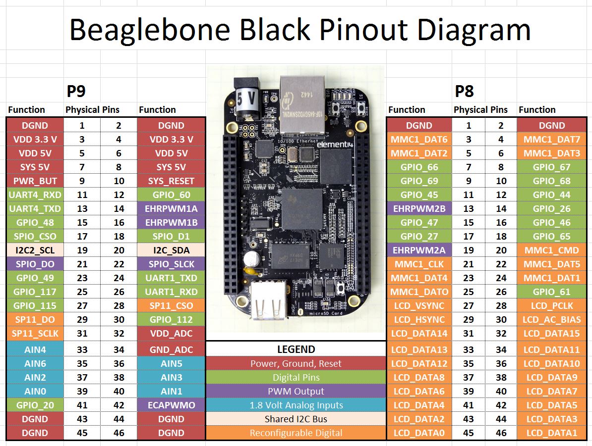
Our pinout from LESSON 1 shows which pins are suitable for digital reads.
Default Pin Configuration for the Beaglebone Black Rev. C.
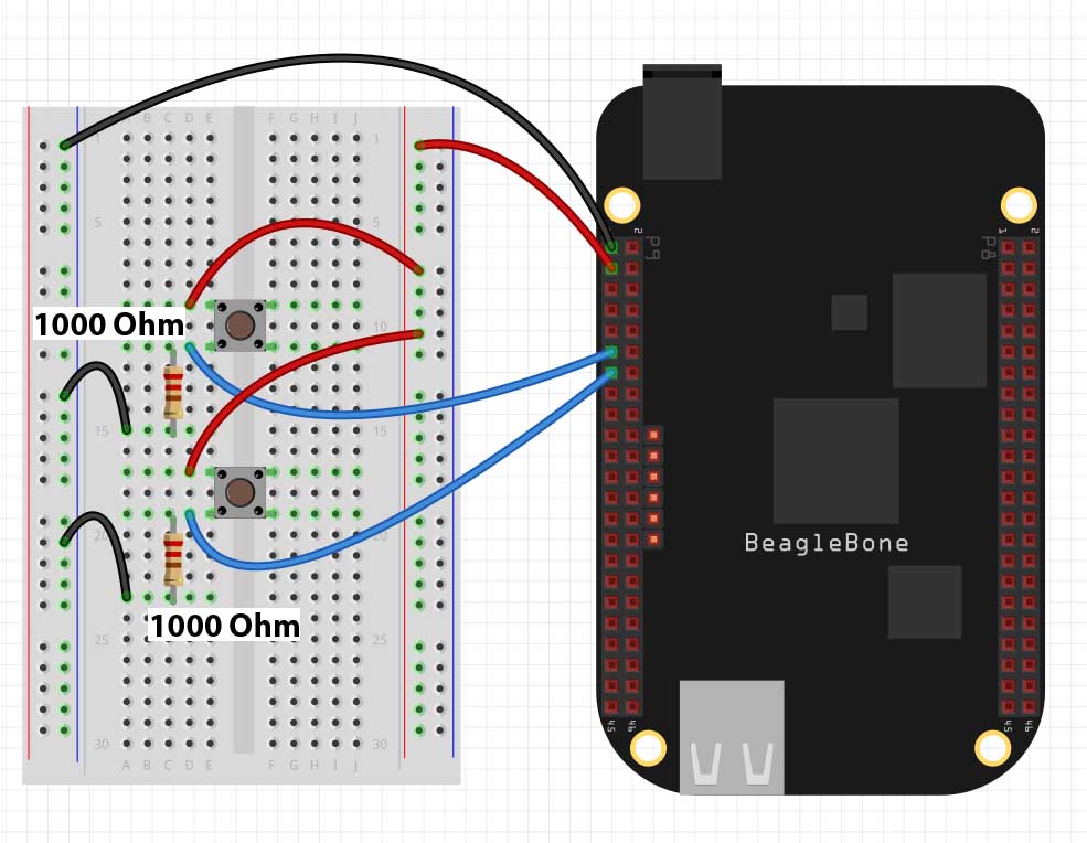
It is the green GPIO pins which we can use for digital reads. In this lesson we will demonstrate the digital read technique using a simple two button circuit. In order to complete this lesson, you should go ahead and build this circuit.
Example of Simple Beaglebone Black Button Circuit
Notice we are using Pin 1 on Header P9 as the ground and Pins 11 and 13 on header P9 s the input pins. Also note the pulldown resistors are 1000 Ohm. It is important to use at least this much resistance. If you do not have 1,000 Ohm resistors, using something larger NOT something smaller.
Once you have the circuit set up we are ready to begin programming.
First up, you need to import the GPIO library. If you have the latest version of Debian Wheezy, you should have the library on your system. If you do not have it you will need to update and upgrade your operating system. To load the library, you will use the python command:
Python
1
importAdafruit_BBIO.GPIO asGPIO
We now need to configure out pins P9_11 and P9_13 as inputs. We do this with the command:
Arduino
1
2
GPIO.setup("P9_11",GPIO.IN)
GPIO.setup("P9_13",GPIO.IN)
Now to read the state of the buttons, we would use the commands:
Arduino
1
2
state1=GPIO.input("P9_11")
state2=GPIO.input("P9_13")
state1 will be True if the top button is pushed, and False if it is not being pushed. Similarly, state2 will be True when the button is being pushed, and False when it is not being pushed.
We can bring these concepts together to make the following program. Play around with the program and see what all you can make it do.
Making The World a Better Place One High Tech Project at a Time. Enjoy!
We use cookies to ensure that we give you the best experience on our website. If you continue to use this site we will assume that you are happy with it.