In Lesson 4 and Lesson 5 we showed how to do digital writes to the GPIO pins using Python. (If you have not picked up your Beaglebone Black Rev. C yet, you can get one HERE) With digital writes, we could generate an output of 3.3 volts or 0 volts. For many applications, we would like analog output, or the in between voltages. The Beaglebone Black, as with most microcontrollers, can not produce true analog output. However, for many applications, an analog output can be simulated by creating a fast on/off sequence where the analog value is simmulated by controlling the ratio of on time and off time. This technique is called Pulse Width Modulation, or more simply, PWM. Consider a 3.3 volt signal, which is turning on and off with a frequency of 50 Hz. A 50 Hz signal has a Period of: Period=1/frequency=1/50=.02 seconds, or 20 milliseconds. If during that 20 millisecond period, the signal was “High” for 10 milliseconds, and “Low” for 10 milliseconds, the signal would act like a 1.65 volt analog signal. The output voltage therefor could be considered the rail voltage (3.3 volts) multiplied by the duty cycle (percentage of time the signal is high.
For the Beaglebone Black, only certain pins can be used for PWM signals.
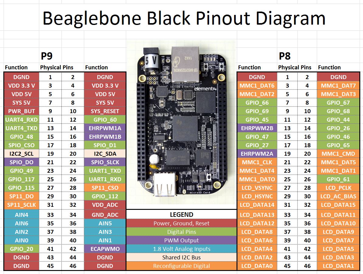
In the chart above, the purple pins are suitable for PWM output. You can see there are 7 pins which can produce PWM signals. In this lesson we show you how to control those pins.
In order to control PWM signals, we are going to use Python and the Adafruid_BBIO Library. Recent versions of Beaglebone Black Rev. C are shipped with the library already part of the operating system. If you are getting errors indicating that you do not have the library, update your operating system to the latest Debian image for the Beaglebone Black.
In order to use PWM in Python, you must load the Adafruit Library. If you have the recent versions of Debian Wheezy for the Beaglebone black, the library will already be on your system. If you do not do an update and upgrade on your operating system.
To begin with, you will need to load the library.
|
1 |
import Adafruit_BBIO.PWM as PWM |
Next up, you will need to start the PWM on the pin you are using. We will use pin “P8_13”. Remember you must use one of the purple colored pins on the chart above. We start the PWM with the following command:
|
1 |
PWM.start("P8_13", 25, 1000) |
This command puts a 1000 Hz signal (Period of 1 mSec) on pin P8_13, with a duty cycle of 25%. This should yield a simulated analog voltage of .84 volts.
We can change the duty cycle after this initial setup with the command:
|
1 |
PWM.set_duty_cycle("P8_13", 90) |
This command would change the duty cycle to 90%, which would simulate a voltage of 3.3 * .9 = 2.97 volts.
You can also change the frequency of the signal using the command:
|
1 |
PWM.set_frequency("P8_13", 100) |
This would change the frequency to 100 Hz (Period of 10 mSec). Changing the frequency does not really affect the net result of PWM in most applications, although it does matter for many servo applications.
After you are done, you can stop the PWM with the command:
|
1 |
PWM.stop("P8_13") |
And always remember to clean up after yourself with:
|
1 |
PWM.cleanup() |
Play around with the Python Program below. Connect a DVM to your Beaglebone Black, and measure the DC voltage at the output pin. The DVM should show your anticipated voltages.
|
1 2 3 4 5 6 7 8 |
import Adafruit_BBIO.PWM as PWM myPWM="P8_13" PWM.start(myPWM, 0, 1000) for i in range(0,5): DC=input("What Duty Cycle Would You Like (0-100)? ") PWM.set_duty_cycle(myPWM, DC) PWM.stop(myPWM) PWM.cleanup() |
Considering that the simulated analog voltage V=3.365 X Duty Cycle, how would modify the program above to ask the user for the Voltage he desires, and then calculate the duty cycle that would give that voltage. Your assignment is to modify the program above where the user inputs desired voltage, and DC is calculated. Use a DVM to check your results