
This is the first in a series of lessons on the Beaglebone Black. Hopefully you have been with us through our earlier series of lessons on the Arduino, Python, and the Raspberry Pi. If you have been through those lessons learning the Beaglebone will be a snap.
If you are going to follow along with us in these lessons, you can go ahead and order your Beaglebone HERE.
To get started, we need to first of all get our mind around all the different pins. I have put together the diagram below for the default pin assignments for the Beaglebone black.
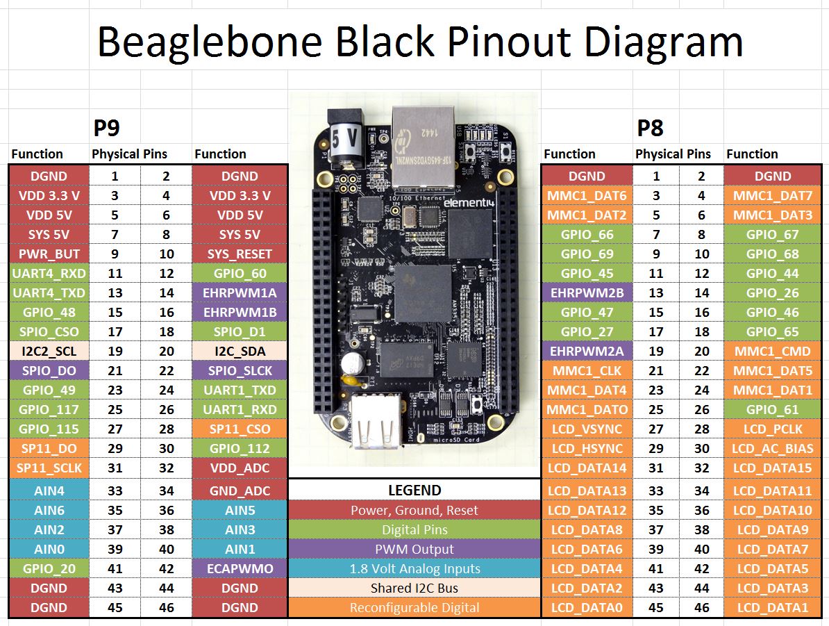
You can see that the Beaglebone has a large number of pins. There are two headers. Make sure you orient your Beaglebone n the same direction as mine in the picture, with the five volt plug on the top. In this orientation, the pin header on the left is referred to as “P9” and the pin header on the right is referred to as “P8”. The legend in the diagram above shows the funtions, or the possible functions of the various pins. First, we have shaded in red the various 5V, 3.3V, 1.8V and ground pins. Note that VDD_ADC is a 1.8 Volt supply and is used to provide a reference for Analog Read functions. The general purpose GPIO pins have been shaded in green. Note some of these green pins can also be used for UART serial communication. If you want to simmulate analog output, between 0 and 3.3 volts, you can use the PWM pins shaded in purple. The light blue pins can be used as analog in. Please note that the Analog In reads between 0 and 1.8 volts. You should not allow these pins to see higher voltages that 1.8 volts. When using these pins, use pins 32 and 34 as your voltage reference and ground, as pin 32 outputs a handy 1.8 volts. The pins shaded in light orange can be used for I2C. The dark orange pins are primarily used for LCD screen applications.