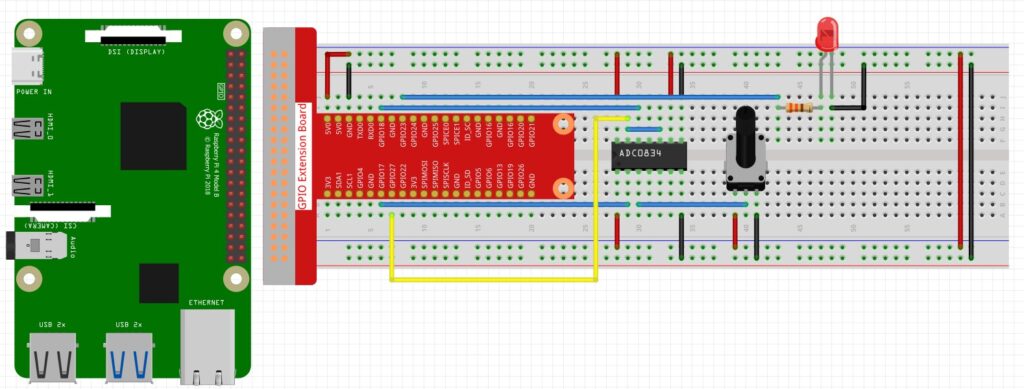
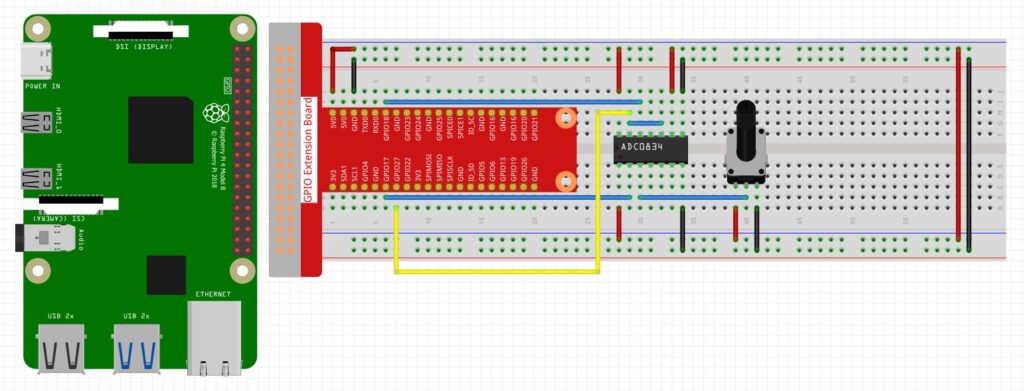
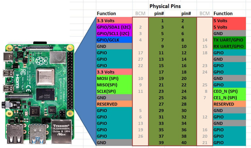
This lesson shows how to connect an LCD1602 to a Raspberry Pi using only 4 wires by I2C. You will need to copy the code below, and create a program called LCD1602.py, and save it in the same folder your main python programs are in.
1 2 3 4 5 6 7 8 9 10 11 12 13 14 15 16 17 18 19 20 21 22 23 24 25 26 27 28 29 30 31 32 33 34 35 36 37 38 39 40 41 42 43 44 45 46 47 48 49 50 51 52 53 54 55 56 57 58 59 60 61 62 63 64 65 66 67 68 69 70 71 72 73 74 75 76 77 78 79 80 81 82 83 84 85 86 87 88 89 90 91 92 93 94 95 96 97 98 99 100 101 | #!/usr/bin/env python3 import time import smbus2 as smbus BUS = smbus.SMBus(1) def write_word(addr, data): global BLEN temp = data if BLEN == 1: temp |= 0x08 else: temp &= 0xF7 BUS.write_byte(addr ,temp) def send_command(comm): # Send bit7-4 firstly buf = comm & 0xF0 buf |= 0x04 # RS = 0, RW = 0, EN = 1 write_word(LCD_ADDR ,buf) time.sleep(0.002) buf &= 0xFB # Make EN = 0 write_word(LCD_ADDR ,buf) # Send bit3-0 secondly buf = (comm & 0x0F) << 4 buf |= 0x04 # RS = 0, RW = 0, EN = 1 write_word(LCD_ADDR ,buf) time.sleep(0.002) buf &= 0xFB # Make EN = 0 write_word(LCD_ADDR ,buf) def send_data(data): # Send bit7-4 firstly buf = data & 0xF0 buf |= 0x05 # RS = 1, RW = 0, EN = 1 write_word(LCD_ADDR ,buf) time.sleep(0.002) buf &= 0xFB # Make EN = 0 write_word(LCD_ADDR ,buf) # Send bit3-0 secondly buf = (data & 0x0F) << 4 buf |= 0x05 # RS = 1, RW = 0, EN = 1 write_word(LCD_ADDR ,buf) time.sleep(0.002) buf &= 0xFB # Make EN = 0 write_word(LCD_ADDR ,buf) def init(addr, bl): # global BUS # BUS = smbus.SMBus(1) global LCD_ADDR global BLEN LCD_ADDR = addr BLEN = bl try: send_command(0x33) # Must initialize to 8-line mode at first time.sleep(0.005) send_command(0x32) # Then initialize to 4-line mode time.sleep(0.005) send_command(0x28) # 2 Lines & 5*7 dots time.sleep(0.005) send_command(0x0C) # Enable display without cursor time.sleep(0.005) send_command(0x01) # Clear Screen BUS.write_byte(LCD_ADDR, 0x08) except: return False else: return True def clear(): send_command(0x01) # Clear Screen def openlight(): # Enable the backlight BUS.write_byte(0x27,0x08) BUS.close() def write(x, y, str): if x < 0: x = 0 if x > 15: x = 15 if y <0: y = 0 if y > 1: y = 1 # Move cursor addr = 0x80 + 0x40 * y + x send_command(addr) for chr in str: send_data(ord(chr)) if __name__ == '__main__': init(0x27, 1) write(4, 0, 'Hello') write(7, 1, 'world!') |


