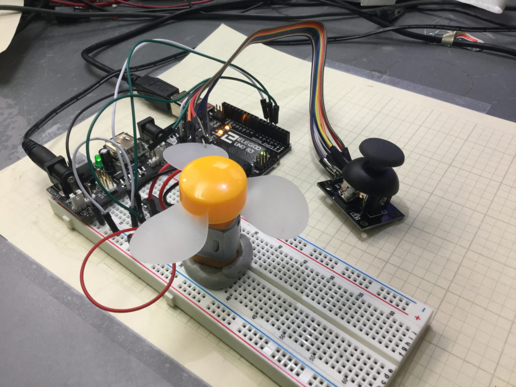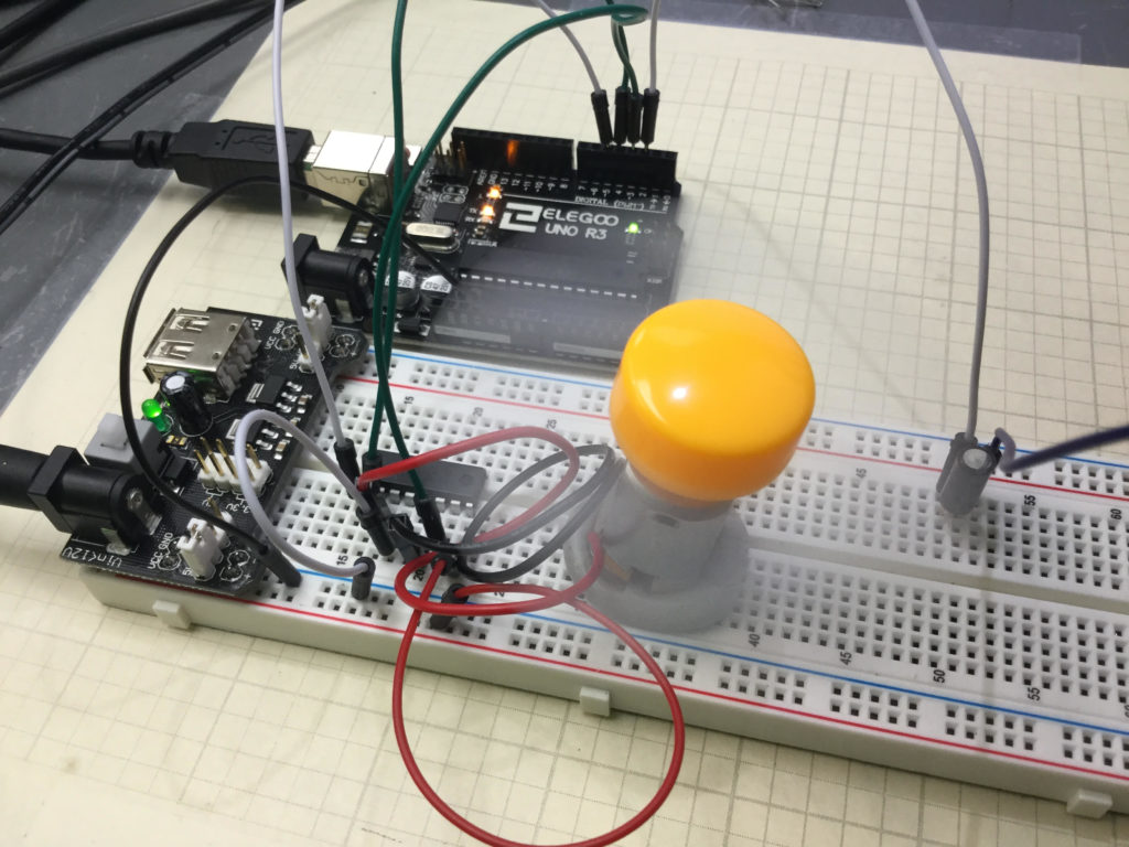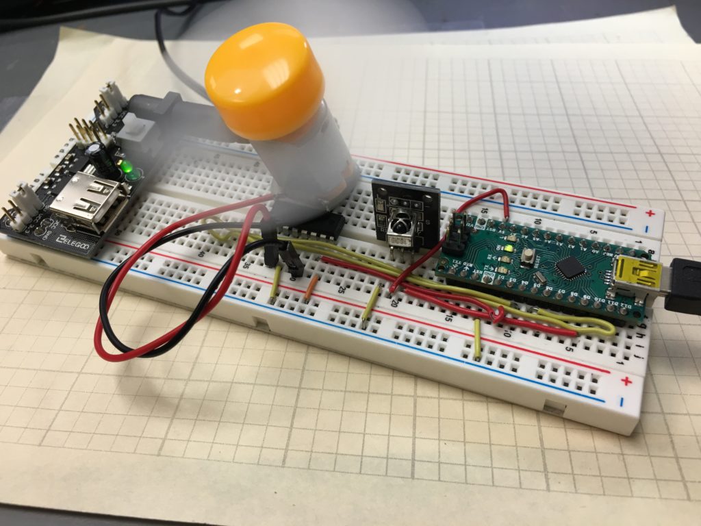
In this lesson we develop a project that allow Remote Control of the speed and direction of a DC Motor. We use an Arduino Nano, and components from the Elegoo Kit. Also, to facilitate a clean build, we use Straight Jumper Wires.
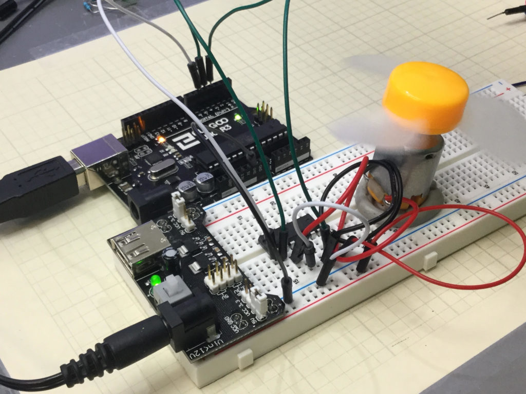
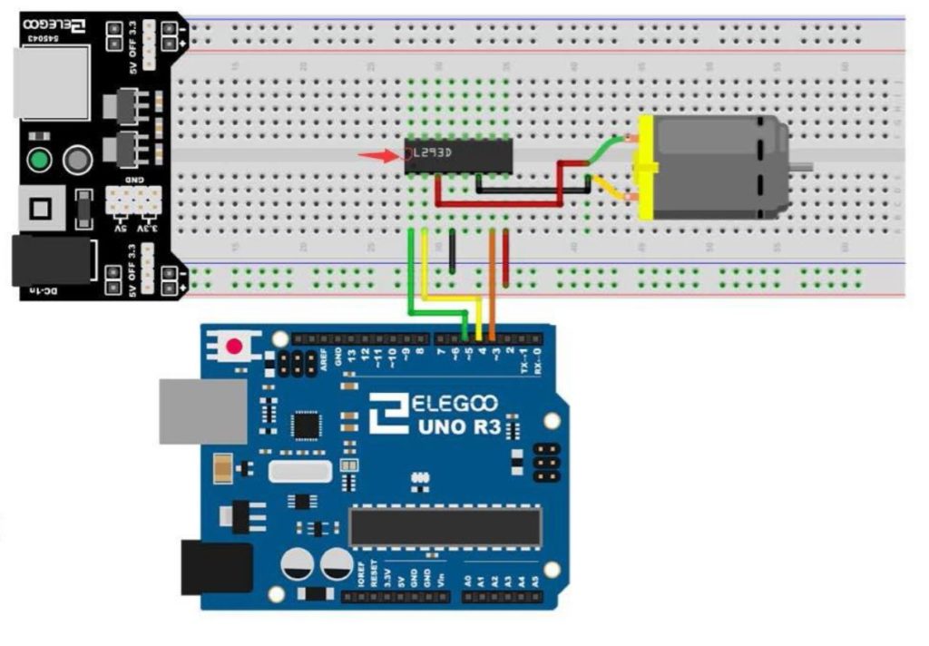
The motor is connected according to this schematic:
Also, the remote control receiver is connected as follows: R on Remote to 5V, G on Remote to Ground, and Y on the Remote to Arduino Digital Pin 9. Go back and check out Tutorial 65 if you need more details on the Remote Module Connections.
In this video we will take you step by step through the build and coding for the project.
The code below is the software we developed in the video.
1 2 3 4 5 6 7 8 9 10 11 12 13 14 15 16 17 18 19 20 21 22 23 24 25 26 27 28 29 30 31 32 33 34 35 36 37 38 39 40 41 42 43 44 45 46 47 48 49 50 51 52 53 54 55 56 57 58 59 60 61 62 63 64 65 66 67 68 69 70 71 72 73 74 75 76 77 78 79 80 81 82 83 84 85 86 87 88 89 90 91 92 93 94 95 96 97 98 99 100 101 102 103 104 105 106 107 108 109 110 111 112 113 114 115 116 117 118 119 120 121 122 123 124 125 126 127 128 129 130 131 132 133 134 135 136 137 138 139 140 141 142 143 144 145 146 147 148 149 150 | #include <IRremote.h> int IRpin=9; IRrecv IR(IRpin); decode_results cmd; String myCom; int speedPin=5; int dir1=4; int dir2=3; int mSpeed=255; void setup() { Serial.begin(9600); IR.enableIRIn(); pinMode(speedPin,OUTPUT); pinMode(dir1,OUTPUT); pinMode(dir2,OUTPUT); digitalWrite(dir1,HIGH); digitalWrite(dir2,LOW); } void loop() { while (IR.decode(&cmd)==0){ } delay(1500); IR.resume(); if (cmd.value==0xFF6897){ myCom="zero"; Serial.println(myCom); } if (cmd.value==0xFF30CF){ myCom="one"; Serial.println(myCom); } if (cmd.value==0xFF18E7){ myCom="two"; Serial.println(myCom); } if (cmd.value==0xFF7A85){ myCom="three"; Serial.println(myCom); } if (cmd.value==0xFF10EF){ myCom="four"; Serial.println(myCom); } if (cmd.value==0xFF38C7){ myCom="five"; Serial.println(myCom); } if (cmd.value==0xFF5AA5){ myCom="six"; Serial.println(myCom); } if (cmd.value==0xFF42BD){ myCom="seven"; Serial.println(myCom); } if (cmd.value==0xFF4AB5){ myCom="eight"; Serial.println(myCom); } if (cmd.value==0xFF52AD){ myCom="nine"; Serial.println(myCom); } if (cmd.value==0xFFA25D){ myCom="pwr"; Serial.println(myCom); } if (cmd.value==0xFF629D){ myCom="v+"; Serial.println(myCom); } if (cmd.value==0xFFE21D){ myCom="fun"; Serial.println(myCom); } if (cmd.value==0xFF22DD){ myCom="rew"; Serial.println(myCom); } if (cmd.value==0xFF02FD){ myCom="play"; Serial.println(myCom); } if (cmd.value==0xFFC23D){ myCom="ff"; Serial.println(myCom); } if (cmd.value==0xFFE01F){ myCom="dn"; Serial.println(myCom); } if (cmd.value==0xFFA857){ myCom="v-"; Serial.println(myCom); } if (cmd.value==0xFF906F){ myCom="up"; Serial.println(myCom); } if (cmd.value==0xFF9867){ myCom="eq"; Serial.println(myCom); } if (cmd.value==0xFFB04F ){ myCom="st"; Serial.println(myCom); } if (myCom=="pwr"){ digitalWrite(dir1,LOW); digitalWrite(dir2,HIGH); analogWrite(speedPin,255); } if (myCom=="fun"){ digitalWrite(dir1,LOW); digitalWrite(dir2,HIGH); analogWrite(speedPin,0); } if (myCom=="ff"){ digitalWrite(dir1,LOW); digitalWrite(dir2,HIGH); analogWrite(speedPin,mSpeed); } if (myCom=="rew"){ digitalWrite(dir1,HIGH); digitalWrite(dir2,LOW); analogWrite(speedPin,mSpeed); } if (myCom=="up"){ mSpeed=mSpeed+15; if (mSpeed>255){ mSpeed=255; } analogWrite(speedPin,mSpeed); } if (myCom=="dn"){ mSpeed=mSpeed-15; if (mSpeed<0){ mSpeed=0; } analogWrite(speedPin,mSpeed); } } |