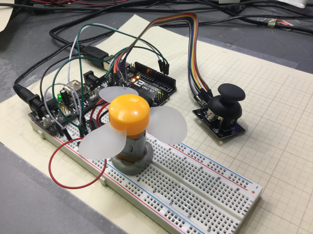
Lesson 37 and 38 showed some preliminary concepts in controlling a DC motor using an arduino and the L293D motor controller. In the video above we show how to control the speed and direction of a simple DC motor using a joystick. In the neutral position, the motor is stationary. Then the speed smoothly increases as you move the joystick forward, until you reach maximum speed.
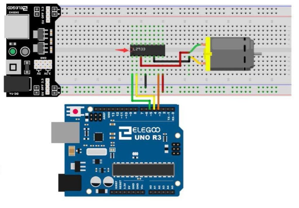
Lesson 37 and 38 showed some preliminary concepts in controlling a DC motor using an arduino and the L293D motor controller. In the video above we show how to control the speed and direction of a simple DC motor using a joystick. In the neutral position, the motor is stationary. Then the speed smoothly increases as you move the joystick forward, until you reach maximum speed. Similarly, in pulling the joystick back from the neutral position, the motor gradually increases speed in the reverse direction. The diagram below shows the basic motor control schematic we are working from.

In the circuit diagram above, we also add a wire to connect the arduino ground to the power supply ground. It is always good to have all components connected to a common ground rail. Of course, you also need to add the joystick controller as shown in the video.
This is the code we used in this
1 2 3 4 5 6 7 8 9 10 11 12 13 14 15 16 17 18 19 20 21 22 23 24 25 26 27 28 29 30 31 32 33 34 35 | int speedPin=5; int dir1=4; int dir2=3; int mSpeed; int jPin=A1; int jVal; void setup() { // put your setup code here, to run once: pinMode(speedPin,OUTPUT); pinMode(dir1,OUTPUT); pinMode(dir2,OUTPUT); pinMode(jPin,INPUT); Serial.begin(9600); } void loop() { // put your main code here, to run repeatedly: jVal=analogRead(jPin); Serial.println(jVal); if (jVal<512){ digitalWrite(dir1,LOW); digitalWrite(dir2,HIGH); mSpeed=-255./512.*jVal+255.; analogWrite(speedPin,mSpeed); } if(jVal>=512){ digitalWrite(dir1,HIGH); digitalWrite(dir2,LOW); mSpeed=(255./512.)*jVal-255.; analogWrite(speedPin,mSpeed); } } |
