In this video lesson we explore using an RFID-RC522 and an RFID tag to lock and unlock our raspberry pi project. This demonstration will include an RGB LED which remains red while the system is locked, and then turns green when the system is unlocked by the RFID tag. Absence of user input, the system will lock again after 5 seconds. The following is the circuit diagram for the project:
Schematic for Raspberry Pi Pico W and RFID module, with LED and Push Buttons
When using the breadvolt, or any battery power supply on a breadboard project, do not turn the power supply on while the Raspberry Pi Pico is connected to USB, as you could generate voltage conflicts. It is an either or. If the USB is connected, the power supply should be OFF. Or if you are going to connect the USB, first turn off the power supply.
For your convenience, the code for the project is included below:
In this lesson we are working on a client server connection. The Arduino is the server, and a python program on a desktop PC is the client. The objective is to control the color of an RGB LED from the client. The client will send data to the server as comma delimited string, like 255,0,255 for RGB. The challenge on the server side is to parse this data so we get integer values of:
R=255
G=0
B=255
In this video lesson we start by simply controlling two LED, a red and green one, from the python client. We then show how we can control an RGB LED by sending the data string from the client, and parsing it on the server side. For your convenience, we include the code here:
The code above needs a ‘secrets.h’ file which includes your WiFi name and password. This is created in the IDE by choosing ‘Add Tab’. Call the new tab ‘secrets.h’, and edit the code below to include your WiFi name and passwords inside the quotes:
1
2
#define SSID "Your WiFi Name"
#define PASS "Your WiFi Password"
Now, on the client side, this is our standard Python client:
Python
1
2
3
4
5
6
7
8
9
10
11
12
13
14
15
16
17
18
19
20
21
22
23
24
25
26
27
28
29
30
31
32
33
34
35
importsocket
# Arduino’s IP address (from Arduino Serial Monitor)
HOST="192.168.88.77"# Use Your Arduino's IP. It will print when
mySocket.settimeout(5.0)# 5 seconds timeout for responses
print("UDP Client started. Enter a color (or 'quit' to exit).")
whileTrue:
# Prompt for a color
#color = input("Enter a color: ").strip() # Remove whitespace
color=input("Enter a color: ")
ifcolor.lower()=='quit':# Exit condition
break
# Send the color to the server
sendColor=color.encode()
mySocket.sendto(sendColor,(HOST,PORT))
print('Sent '+color+' to HOST',HOST,PORT)
# Try to get a response, skip on timeout
try:
response,server_address=mySocket.recvfrom(1024)
print("Server response:",response.decode())
exceptsocket.timeout:
print("No response received from server within 5 seconds")
# Close the socket
mySocket.close()
print("Socket closed")
With this code for creating a client and server, and then parsing comma delimited text, you can easily add the code needed to control the RGB LED color to the arduino program.
In this video we give you a homework assignment to create a dimmable RGB LED. You must set color and brightness using the IR remote. In Tutorial 68 we will take you through the build, and show you the solution. I hope you will really try your best to do it on your own before you check out my solution.
This first video shows just the results of this extremely exciting project! Watch the first video if you want a quick summary showing the working project.
The second video, below shows an in depth step-by-step tutorial on how to make the project work.
OK, in the first 14 lessons we were laying the ground work for circuits and programming. Now it is time we had a little fun. This project will show you how to do an insanely cool circuit based on what you have learned already. This time we are going to use the RGB LED circuit you worked on in Lesson 13 and Lesson 14, but this time you will set the color based on the color seen by a color sensor! That is right, we will incorporate a color sensor into the circuit. If the color sensor sees red, the LED will turn red. If it sees blue, the LED will turn blue. Our challenge in this project is to make the sensor match as many colors as well as possible.
We will use an arduino color sensor to set the color of the RGB LED
There are a couple of things you will need for this project in addition to the arduino, breadboard, and RGB LED we have been using so far. The good news is the components are very affordable and can be easily ordered from amazon. First up you will need the Virtuobotix Color Sensor which you can order HERE. To connect the color sensor to your arduino you will need some male/female connecting wires, which you can order HERE. You probably have the rest of the things you need, but I will give a complete list at the end of this lesson.
For the LED side of things you will want to use the same circuit from Lesson 13 and Lesson 14. As a refresher, here is the schematic;
Circuit used to control RGB LED from an arduino
Now for this project, instead of getting the desired color from the user via the serial port, we will set the LED color by having it match colored cards we place in front of the sensor. So, we will need to figure out how to operate the sensor. It is really pretty straighforward. First up, we have to hook it to the arduino. That is probably easiest done by following this table, rather than me trying to draw a picture:
Connecting the Color Sensor to the Arduino
Color Sensor Pin
Arduino Pin
S0
GND
S1
5V
S2
pin 7
S3
pin 8
OUT
pin 4
VCC
5V
GND
GND
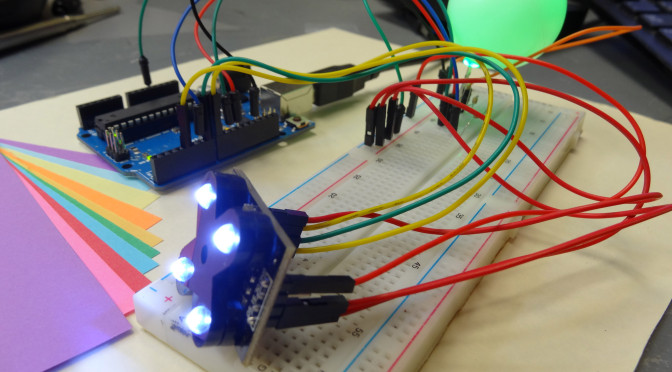
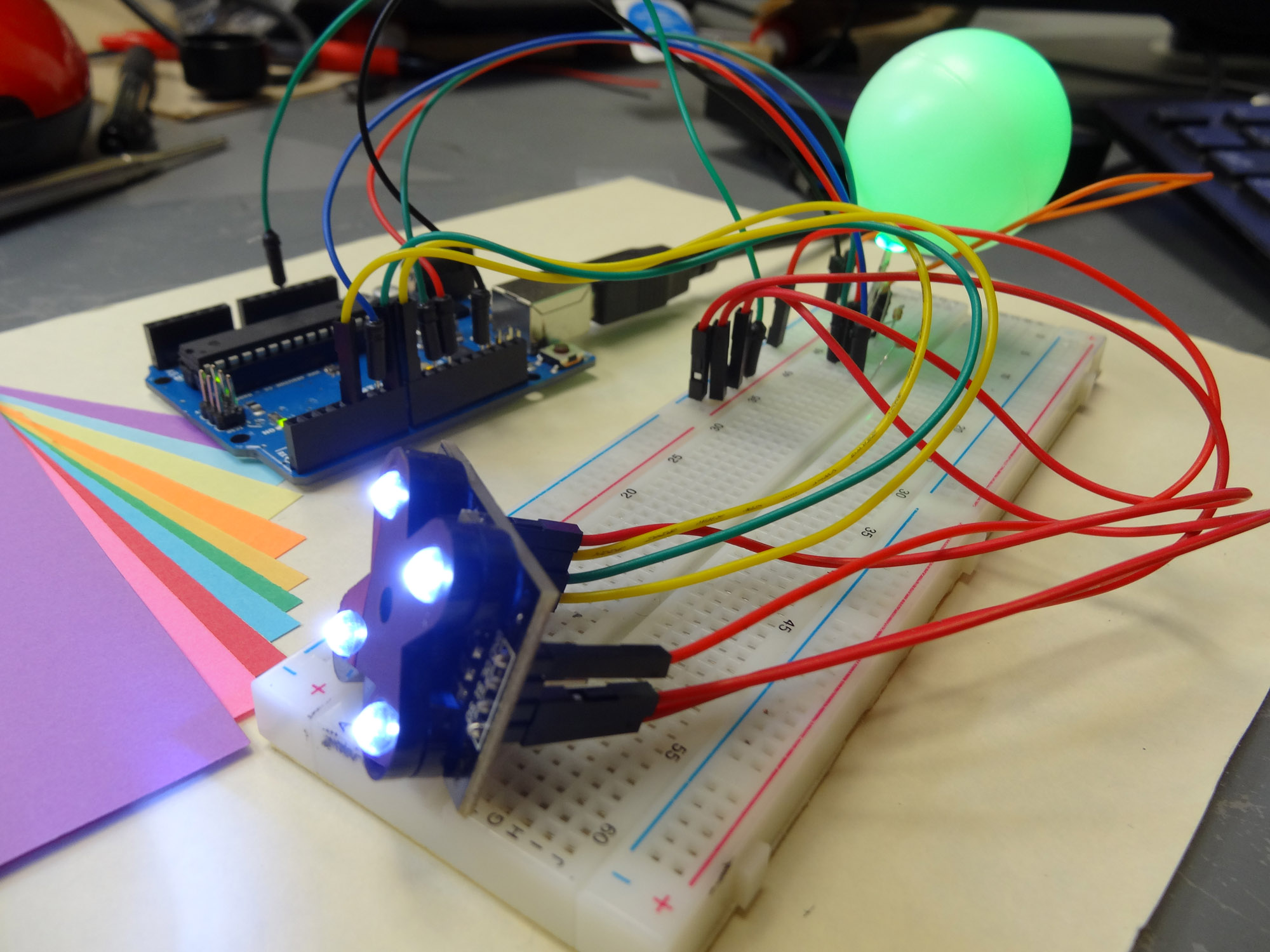
Hopefully that is clear. Remember, you must use the male/female wires described above to connect the Color Sensor to the Arduino. Unfortunately, the sensor is too big to connect to a standard size breadboard. Use the table above to carefully make the connections, but after you are done your circuit should look like this:
Color Sensor and RGB LED connected to the Arduino
There are lots of wires, so double check your work against the table above.
Now, this is the way the senor works. It will make three different readings indicating the relative “strength” of the three primary colors . . . Red, Green and Blue. Never fear, if you know the strength of the primary colors, you can figure out any color as they will just be different “mixes” of red, green and blue.
Which color is read depends on the voltages you write to the S2 and S3 pins, according to this table:
S2
S3
Color Read
LOW
LOW
Red
LOW
HIGH
Blue
HIGH
HIGH
Green
To actually make a measurement, you need to select which color strength you want to read by doing digital writes to pins S2 and S3 according to the pins above. Then you read the color strength on the sensor OUT pin, which we have connected to Arduino pin 4. To make the measurement, you need to make a pulseIn measurement at pin 4 on the arduino. The pulseIn measurement is an arduino command that looks at the pin you specify, and looks for a pulse, and returns to you a number representing the length in microseconds of the pulse seen at the pin specified. For example, lets say we already declared a variable pulseWidth to hold the measured value. The following code would allow us to measure the pulseWidth at the outPin (make sure you have declared both variables, and you should set the pinMode of outPin to be an INPUT, since you are reading from it;
Arduino
1
pulseWidth=pulseIn(outPin,LOW);//Measure length of a LOW pulse at pin outPin
This measurement will return a value between 0 an 102,400. Because of this, you need to be sure to declare pulseWidth variable an unsigned int. Normal integers can only hold numbers up to +/- 32,768 an unsigned int allows only positive numbers but allows numbers up to 4,294,967,295.
The number that is returned which we put in the variable pulseWidth above can be interpreted as such: The lower the number, the stronger the color being read. The larger the number, the weaker the color.
We need to somehow convert this rather odd number into something that means something in the real world. Well, when we write values to an RGB LED we want them to be between 0 and 255. Also, that is a fairly standard scale to report RGB colors . . . by giving the relative strength of the compoents of R, G, and B on a scale from 0 to 255. First we need to convert 0 to 102,400 to this range. 102,400/400 = 256. Almost exactly what we want! But we need to subtract one. So, we could say that rColorStrength = (pulseWidth/400) – 1. That gets us a number between 0 and 255. Only problem is, remember that in the original pulseWidth, big numbers mean weak colors and small numbers mean strong colors, so we need to fix that. We could fix it by now saying:
rColorStrength = (255 – rColorStrength);
That simply adjusts things so that big numbers now mean strong colors. Also, you can see this example would be for reading red. You would need to repeat by setting S2 and S3 to also create gColorStrenght and bColorStrength for green and blue.
So, with this little bit of math we should have what we need to actually read R, G, and B values that fairly accurately represent the color the sensor is seeing. In the video I go through the code. I am not posting the code on this one because you need to think through it and if you get stuck, the video shows you each step.
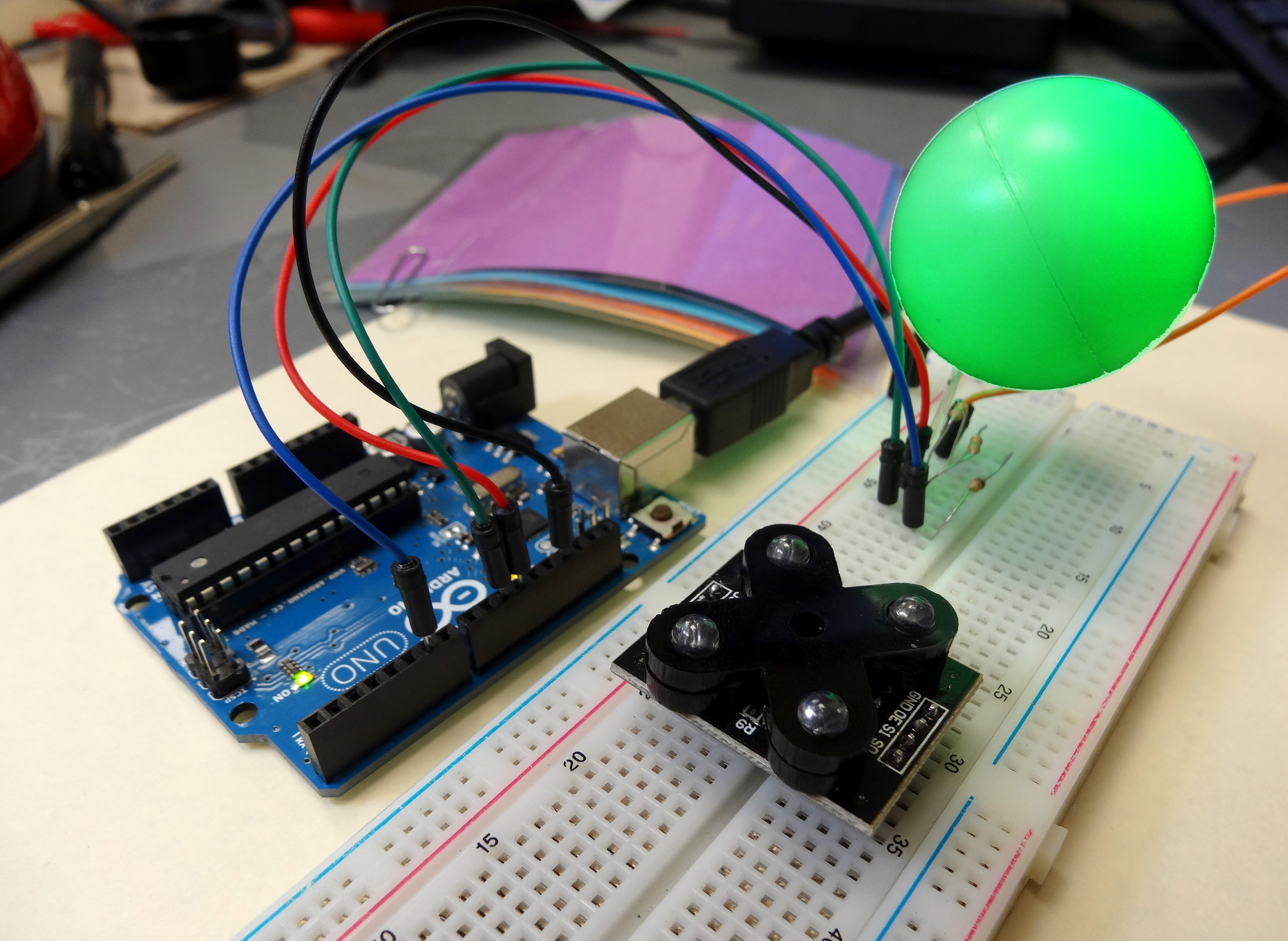
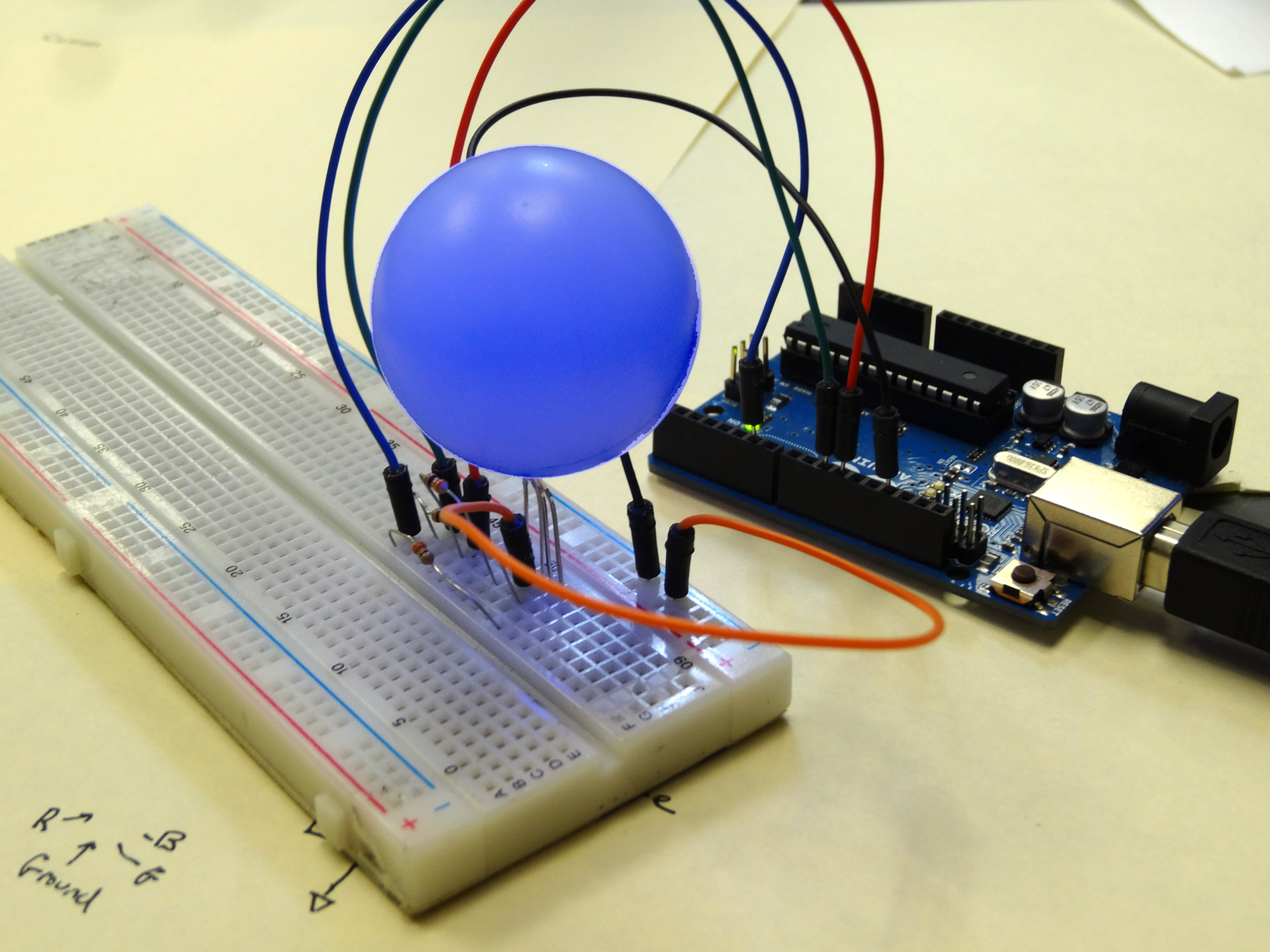
In our LED project in Lesson 13, we controlled the color of the LED by changing lines of code in the program. As you know, you really want to do that sort of thing by interacting with the user over the serial port. So, in this project, we are going to have the user set the color by indicating his preferred color in the serial monitor. Notice in our new picture below we have covered the LED with a ping pong ball. We did this so the LED will show better in the video, but after doing it, I really like it! It makes a cool little lamp. You can do this by creating a small hole the size of the LED in the ping pong ball, and then just mounting the ball on the LED. Cool stuff!
We have added a ping pong ball to the top of our RGB LED.
This project uses the same circuit we set up in Project 13. We will just be changing the code.
Circuit used to control RGB LED from an arduino
So, for this project, we will want the user to input his desired color for the LED. Then we will make the LED change to the color he requested. In order to do this, we need to learn a new programming command called the if statement. The if statement has a clause, or group of commands between a set of curly brackets. It executes those commands only if a condition is met. An if statement in arduino would look like this:
Arduino
1
2
3
4
5
if(somecondition){
putallyourcommandsbetweenthecurlybrackets
}
The commands between the curly brackets will be executed if the condition inside the parenthesis is true. Lets consider you had two variables, a and b. Lets say you only wanted to execute the commands in the clause if a is > or = to b. In that case you would put that condition in the parenthesis and your code would look like this:
Arduino
1
2
3
4
5
if(a>=b){
putallyourcommandsbetweenthecurlybrackets
}
The arduino would only execute the code if the condition was true. Otherwise it would jump to the first line of code after the closing curly bracket. There are a number of different condition tests that can be used in the parenthesis:
Arduino
1
2
3
4
5
6
7
a==b// Tests if a is eqaul to b. Note you must use TWO equal signs
a!=b//Tests if a in not equal to b.
a<b//Tests if a is less than b
a>b//Tests if a is greater than b
a<=b//Tests if a is less than or equal to b
a>=b//Tests if a is greater than or equal to b
You can combine more than one condition by using the logical operators “and” or “or”. In arduino the symbol for “and” operation is && and the symbol for “or” operator is ||. (This is the symbol above the backslash on the keyboard). So you could have a condition where a is greater than b AND a is greater than c. This would look like:
Arduino
1
2
3
4
5
if(a>b&&a>c){
putyourcommandshere
}
OK, so that is how if statements and conditional work. A key thing is that you have to remember than when you are testing for equality in an if statement, you use two equal signs. One of the common mistakes I see students make is to forget and just use one equal sign in a conditional.
What you will want to do now is write a program that will ask the user what color he would like the LED to be. In the prompt let him know that his choices are Red, Green, or Blue. Then turn the LED that color. You should also include a “test” . . . if he does not choose one of the allowed choices, he must choose again. Do your best to develop the code on your own, but if you get stuck, peak at my code below. You should not copy and paste my code, but just use it as a guide if you get stuck.
Arduino
1
2
3
4
5
6
7
8
9
10
11
12
13
14
15
16
17
18
19
20
21
22
23
24
25
26
27
28
29
30
31
32
33
34
35
36
37
38
39
40
41
42
43
44
45
46
47
48
49
intredPin=11;//set red LED pin to 11
intgreenPin=10;//set green LED pin to 10
intbluePin=6;//set blue LED pin to 6
intbrightness=255;//Set brightness to 75
StringcolorChoice;//Will hold users input of color choice
voidsetup(){
// put your setup code here, to run once:
Serial.begin(9600);//Turn on Serial port
pinMode(redPin,OUTPUT);//Set redPin to be an output
pinMode(greenPin,OUTPUT);//Set greenPin to be an output
pinMode(bluePin,OUTPUT);//set bluePin to be an output
}
voidloop(){
Serial.println("What color would you like the LED? (red, green, or blue)");//Prompt user for color
while(Serial.available()==0){}//Wait for input
colorChoice=Serial.readString();
if(colorChoice=="red"){
analogWrite(redPin,brightness);//turn on red pin
analogWrite(greenPin,0);//turn off green pin
analogWrite(bluePin,0);//write off blue pin
}
if(colorChoice=="blue"){
analogWrite(redPin,0);//turn off red pin
analogWrite(greenPin,0);//turn off green pin
analogWrite(bluePin,brightness);//write on blue pin
}
if(colorChoice=="green"){
analogWrite(redPin,0);//turn off red pin
analogWrite(greenPin,brightness);//turn on green pin
Serial.println("That is not a valid color choice, please try again");
Serial.println("");
}
}
OK, now your assignment is to move forward and have the program have more options for colors. Have it where you can turn the LED Red, Green, Blue, Cyan, Magenta, Yellow, Orange, Purple, Pink. Do some research on the internet to make sure you are really hitting these colors. Part of your grade will be how well you match the colors.
Making The World a Better Place One High Tech Project at a Time. Enjoy!
We use cookies to ensure that we give you the best experience on our website. If you continue to use this site we will assume that you are happy with it.Ok