


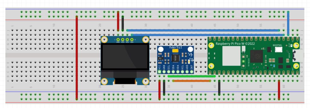
In this video lesson I show you how to remove long term steady state error from the tilt values calculated from the MPU6050 IMU. We are using the following schematic for our prototype.

For your convenience, this is the code we developed in the video.
|
1 2 3 4 5 6 7 8 9 10 11 12 13 14 15 16 17 18 19 20 21 22 23 24 25 26 27 28 29 30 31 32 33 34 35 36 37 38 39 40 41 42 43 44 45 46 47 48 49 50 51 |
from imu import MPU6050 from machine import I2C,Pin import math import time i2c=I2C(0, sda=Pin(16), scl=Pin(17), freq=400000) mpu = MPU6050(i2c) rollG=0 pitchG=0 rollComp=0 pitchComp=0 errorR=0 errorP=0 yaw=0 tLoop=0 cnt=0 while True: tStart=time.ticks_ms() xGyro=mpu.gyro.x yGyro=-mpu.gyro.y zGyro=mpu.gyro.z xAccel=mpu.accel.x yAccel=mpu.accel.y zAccel=mpu.accel.z rollG=rollG+yGyro*tLoop pitchG=pitchG+xGyro*tLoop rollA=math.atan(xAccel/zAccel)/2/math.pi*360 pitchA=math.atan(yAccel/zAccel)/2/math.pi*360 rollComp= rollA*.005 + .995*(rollComp+yGyro*tLoop)+errorR*.005 pitchComp= pitchA*.005 + .995*(pitchComp+xGyro*tLoop)+errorP*.005 errorP=errorP + (pitchA-pitchComp)*tLoop errorR=errorR + (rollA-rollComp)*tLoop cnt=cnt+1 if cnt==10: cnt=0 print('RA: ',rollA,'PA: ',pitchA,'RC: ',rollComp,'PC: ',pitchComp) #print('RA: ',rollA,'RC: ',rollComp) tStop=time.ticks_ms() tLoop=(tStop-tStart)*.001 |


