So far in our programming we have set the variables inside of the program, usually up at the top. In order to change the number of times the LED’s blink, we would change the lines of code that set those variables. This is OK for playing around, but you can see that if you want other people to use your programs you can not have them playing around with your code. You need to be able to get input from the user without modifying the code. We can do that using the Serial Port. Just like we can print information to the user using the Serial Port, we can also get information from the user using the serial port.
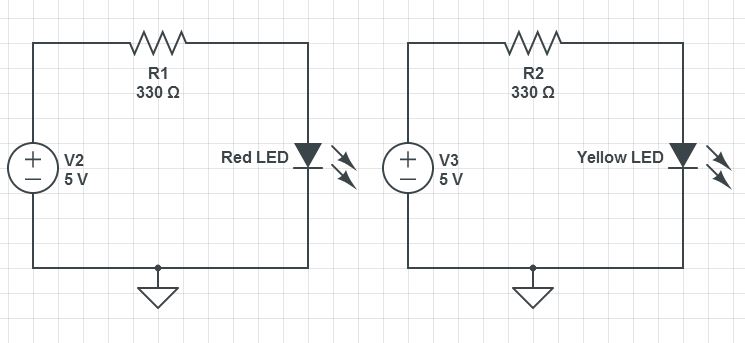
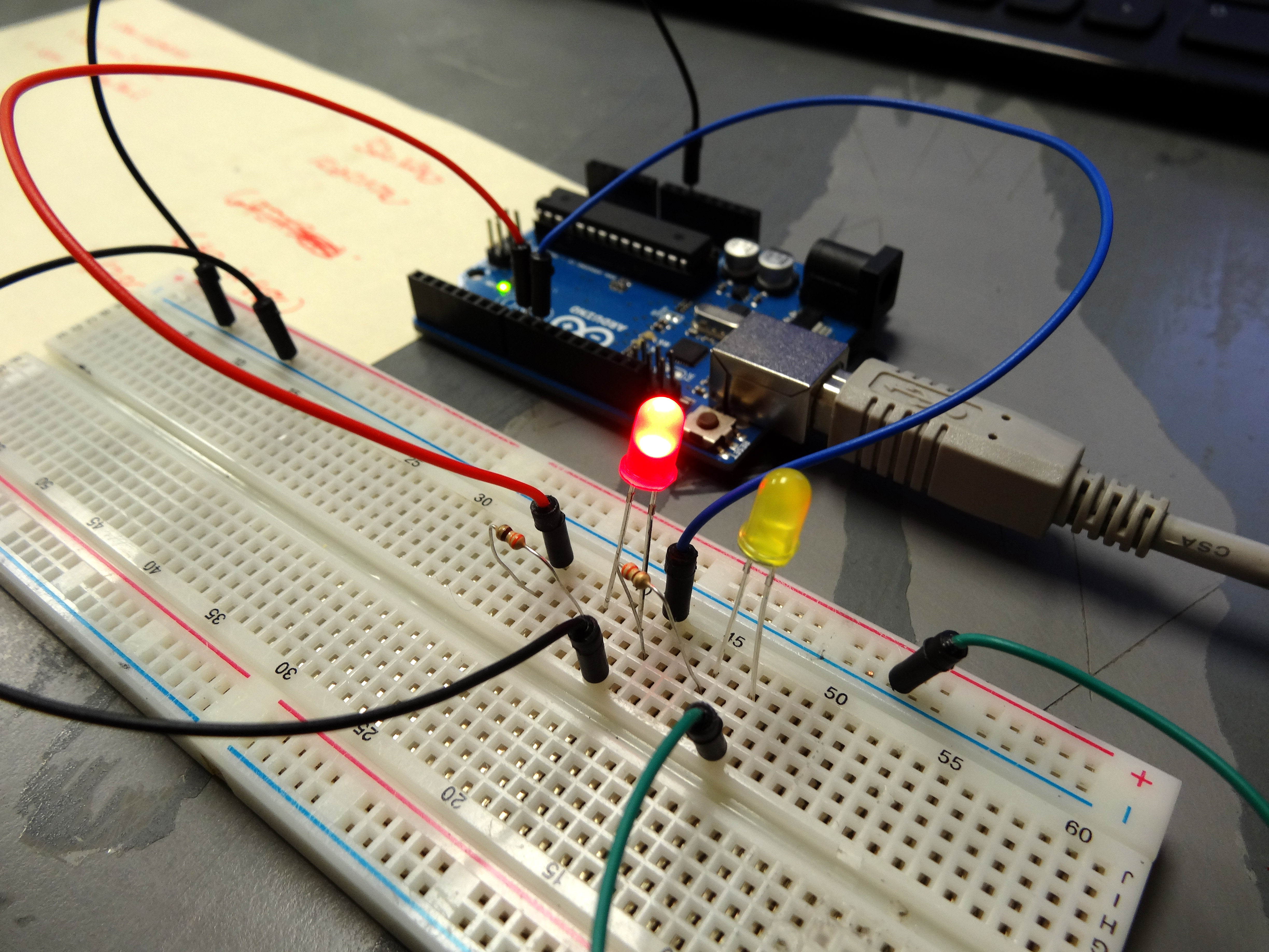
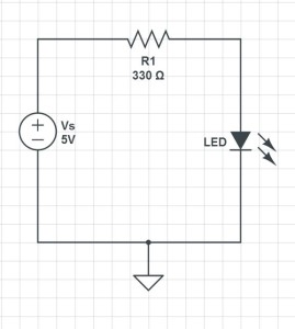
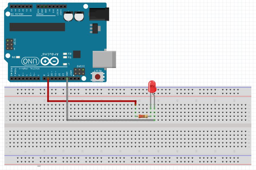
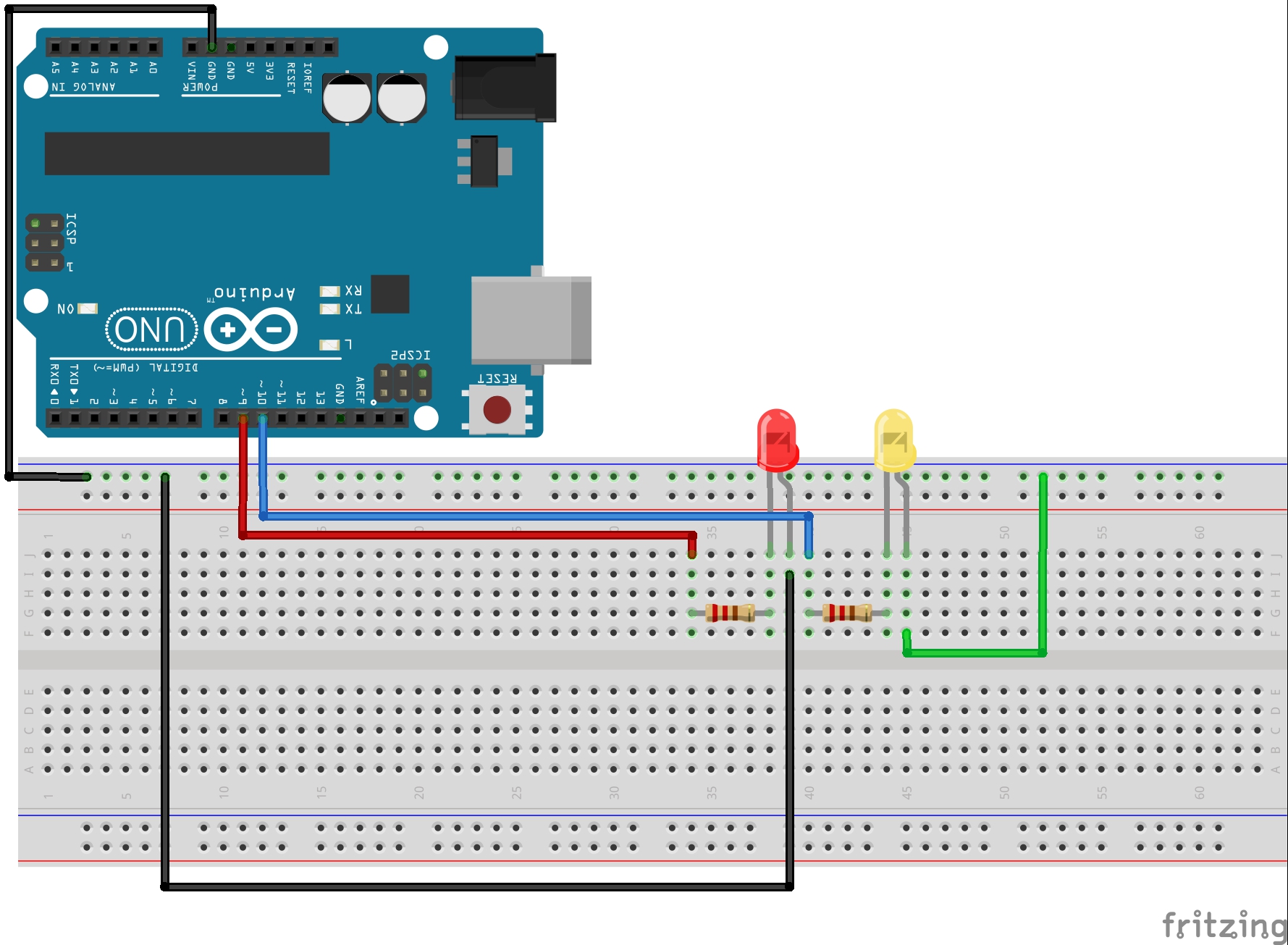
In these exercises we will continue to use the circuit created in Arduino Lesson 3. If you need help in putting the circuit together, go back and review that lesson. Here is a diagram of the circuit we are working with.
Also, as a reminder, here is the code we have been working with that incorporates all the things we have learned so far. I am including this code so you can look at it if you get stuck, and to serve as an example for the work you do. To learn programming though, you need to be typing in your own code, making mistakes, and then finding an correcting your mistakes. You will not learn programming if you simply go through these lessons copying and pasting my code.
|
1 2 3 4 5 6 7 8 9 10 11 12 13 14 15 16 17 18 19 20 21 22 23 24 25 26 27 28 29 30 31 32 33 34 35 36 37 38 39 40 |
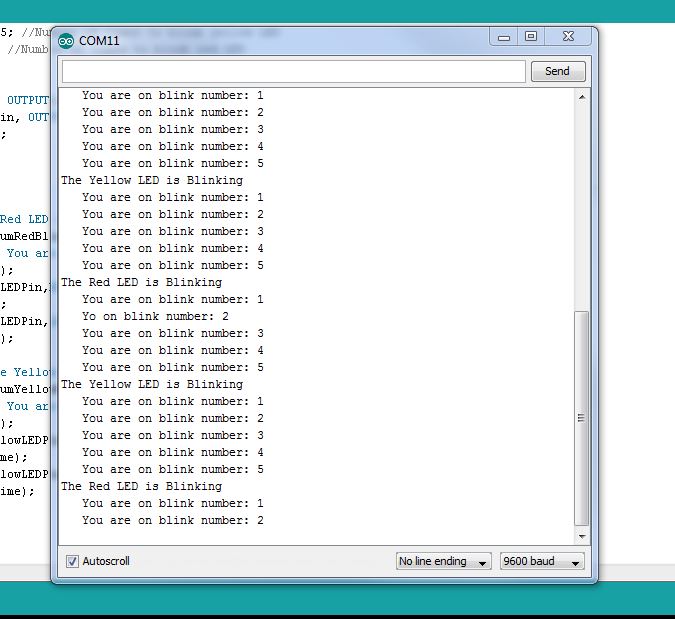
int redLEDPin=9; //Declare redLEDPin an int, and set to pin 9 int yellowLEDPin=10; //Declare yellowLEDPin an int, and set to pin 10 int redOnTime=250; //Declare redOnTime an int, and set to 250 mseconds int redOffTime=250; //Declare redOffTime an int, and set to 250 int yellowOnTime=250; //Declare yellowOnTime an int, and set to 250 int yellowOffTime=250; //Declare yellowOffTime an int, and set to 250 int numYellowBlinks=5; //Number of times to blink yellow LED int numRedBlinks=5; //Number of times to blink red LED String redMessage="The Red LED is Blinking"; //Declaring a String Variable String yellowMessage="The Yellow LED is Blinking"; //Declaring a String Variable void setup() { Serial.begin(115200); // Turn on the Serial Port pinMode(redLEDPin, OUTPUT); // Tell Arduino that redLEDPin is an output pin pinMode(yellowLEDPin, OUTPUT); //Tell Arduino that yellowLEDPin is an output pin } void loop() { Serial.println(redMessage); for (int j=1; j<=numRedBlinks; j=j+1) { // Start our for loop Serial.print(" You are on Blink #: "); Serial.println(j); digitalWrite(redLEDPin,HIGH); //Turn red LED on delay(redOnTime); //Leave on for redOnTime digitalWrite(redLEDPin,LOW); //Turn red LED off delay(redOffTime); //Leave off for redOffTime } Serial.println(" "); Serial.println(yellowMessage); for (int j=1; j<=numYellowBlinks; j=j+1) { // Start our for loop Serial.print(" You are on Blink #: "); Serial.println(j); digitalWrite(yellowLEDPin,HIGH); //Turn yellow LED on delay(yellowOnTime); //Leave on for yellowOnTime digitalWrite(yellowLEDPin,LOW); //Turn yellow LED off delay(yellowOffTime); //Leave off for yellowOffTime } Serial.println(" "); } |
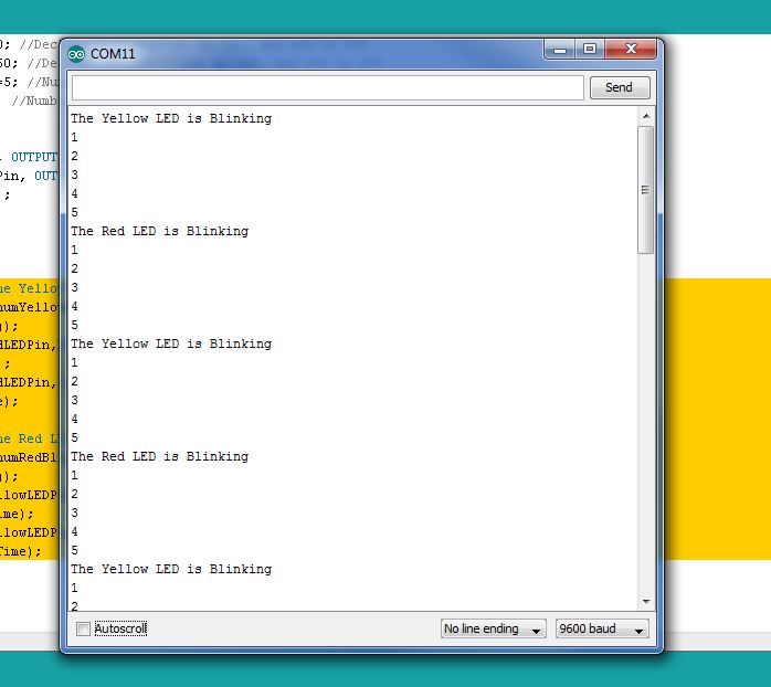
OK, look over this code and review what we have learned so far. At the top of the program we declare our variables, and we assign values to them. So far we have worked with variables of type int and type String. Then in the void loop we start our serial port, and we set our two arduino pins to OUTPUT. In the void loop we have built two for loops . . . one to blink the red LED and then one to blink the yellow LED. The parameters used in the for loop like how many times to blink and how long each blink should be are all defined at the top of the program.
As we mentioned at the beginning, it is OK to start out doing things this way, but at some point you need to be getting your parameter values from the user, and not hard coding them into the program. You would like the program to ask the user how many times he would like to blink the red LED, and then ask how many times he would like to blink the yellow LED. This is really pretty easy to do, and we do it over the serial port, very similar to how we learned to print in lesson 5.
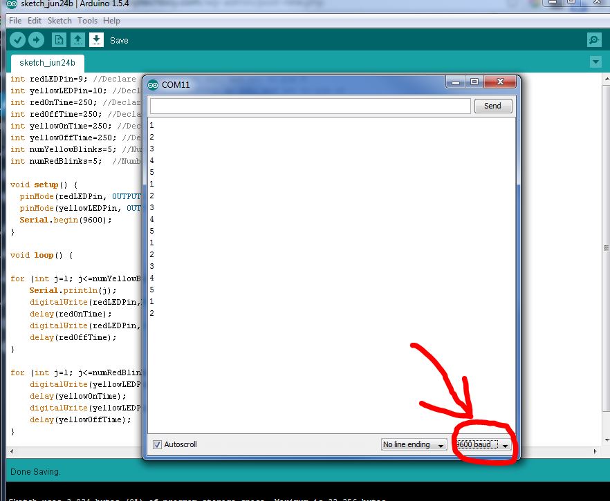
In order to get input from the user, you need to make sure that you have turned your serial port on in your void setup. You do that with a Serial.begin(9600); command, as seen in the code above. You always need to have this command in your void setup() if you are going to print to the serial port or read from it. Now, in order to get input from the user, you need to do three things:
- Prompt the User for the Input
- Wait for the User to Enter the Input
- Read the information from the serial port
In the program above, lets say that in our void loop each time through the loop we want to prompt the user for how many times he wants the red LED to blink and then after that prompt him for how many times he wants the yellow LED to blink. In this scenario, we are now getting the parameters from the user instead of hard wiring them into the program. In this case, we still have to declare our varialbes, but we do not need to assign values to them. Hence in the example above the code:
|
1 2 |
int numYellowBlinks=5; //Number of times to blink yellow LED int numRedBlinks=5; //Number of times to blink red LED |
Should be taken out and replaced with:
|
1 2 |
int numYellowBlinks; //Number of times to blink yellow LED int numRedBlinks; //Number of times to blink red LED |
You see, now we are only declaring our variables. We are not assigning values to them, because we will be getting the values from the user. It is important, however, that any variables that we will use still need to be declared.
Now in our void loop() this would be the code to get from the user the number of times he would like to blink the LED.
|
1 2 3 4 |
Serial.println("How Many Times Do You Want the Red LED to blink?"); //Prompt User for Input while(Serial.available()==0) { // Wait for User to Input Data } numRedBlinks=Serial.parseInt(); //Read the data the user has input |
There is a lot going on in these few lines of code, and lots of new things for you to learn, so lets unpack it pretty carefully. The first line should be familiar to you. You are just printing to the serial monitor a message to the user that you are waiting for input. In this case he will see a message asking him to put in a number. Now, we have to remember that the computer can work much faster than a person, so when a computer asks a person to do something, it is important for the computer to sit and wait for the person to complete it. This is done in the second and third lines of code above. This is an example of a while loop. You can see the while loop has a clause associated with it that starts and ends with the curly brackets. The program will continue to execute what is between these curly brackets as long as the condition that is in the parenthesis is true. So a while loop is sort of like a for loop, except the while loop can continue to loop forever as long as the condition in the parenthesis is true. So, we need to understand the ‘condition’ part of the code above, which is Serial.available()==0. This is not as confusing as it looks. Serial.available() is a function that when you call it, it returns a ‘1’ if the user has input data, and a ‘0’ if the user has not input data. So, if the user has not input data, Seraial.available() will be 0, the condition will be true, and the program will stay in the while loop.
So the bottom line is that
|
1 |
while(Serial.available()==0) { } |
will sit and loop forever waiting for the user to input the data. When the user inputs the data, it will them move on to the next lines of code. Notice that we do not do anything in the while loop because there are no commands between the two curly brackets. The purpose of this line of code is simply to get the program to stay at that point until the user inputs his data.
Now at the point the user does input the data, Serial.avaialbe() will become ‘1’, and the program moves to the next line of code. The next line of code,
|
1 |
numRedBlinks=Serial.parseInt(); |
is the line that actually reads the data. Serial.parseInt() reads the number the user input, and then that number is assigned to the variable numRedBlinks. When you are reading an integer from the serial port, you use Serial.parseInt(). There are different commands for reading other variable types. You can imagine that if you were reading a floating number, you would user Serial.parseFloat(). To read a string you would user Serial.readString(). The important point is that you need to use the correctly precise command for the type of data you are trying to read.
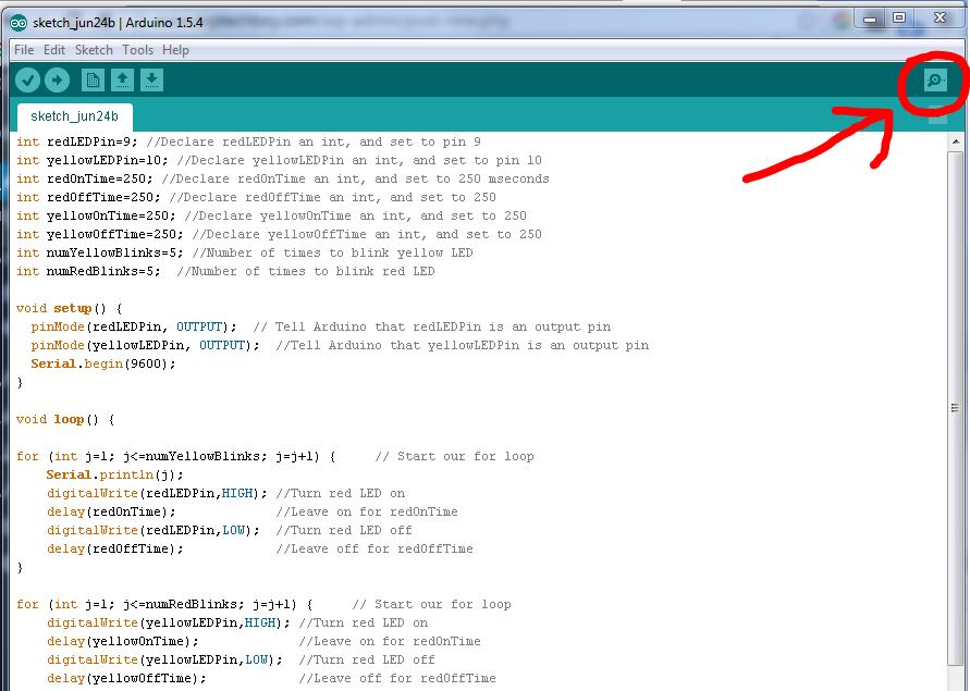
OK, so put that code into your program at the start of the void loop() and also make a similar sequence of code to get from the user the numYellowBlinks. After you have that working also get other parameters from the user like the various blink time variables. You should play around with this and get comfortable getting input from the user. When you run the code, remember to click the icon in the upper right of the arduino IDE to get the serial monitor to pop up. You should see the prompt in the Serial Monitor, and you should enter your number in the small box, and then click send, or press the enter key.