Tag Archives: Lessons

Lesson 11: Arduino Circuit to Dim LED with Potentiometer

Arduino Dimmable LED
Arduino Circuit for Dimming an LED

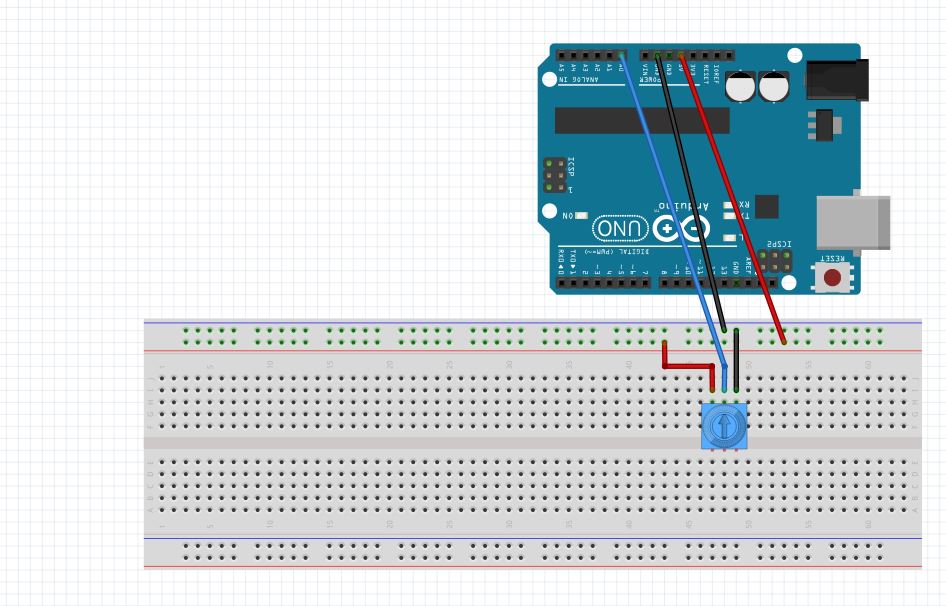
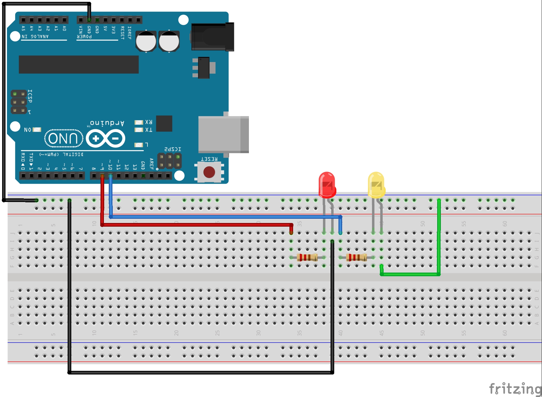
In Lesson 8 you learned to write analog voltages on the Arduiono, and in Lesson 10 you learned to read analog voltages from the arduino. In this lesson we will combine what you did in lessons 8, 9, and 10 to create an LED with adjustable brightness. The brightness will be set based on the position of the potentiometer. In order to do this, we need to set the potentiometer up as a voltage divider, and we need to drive the LED from one of the analog pins. For this example, I am using pin 9. The circuit schematic I am using is shown below.

LED Arduino Circuit
This Schematic Creates a Dimable LED

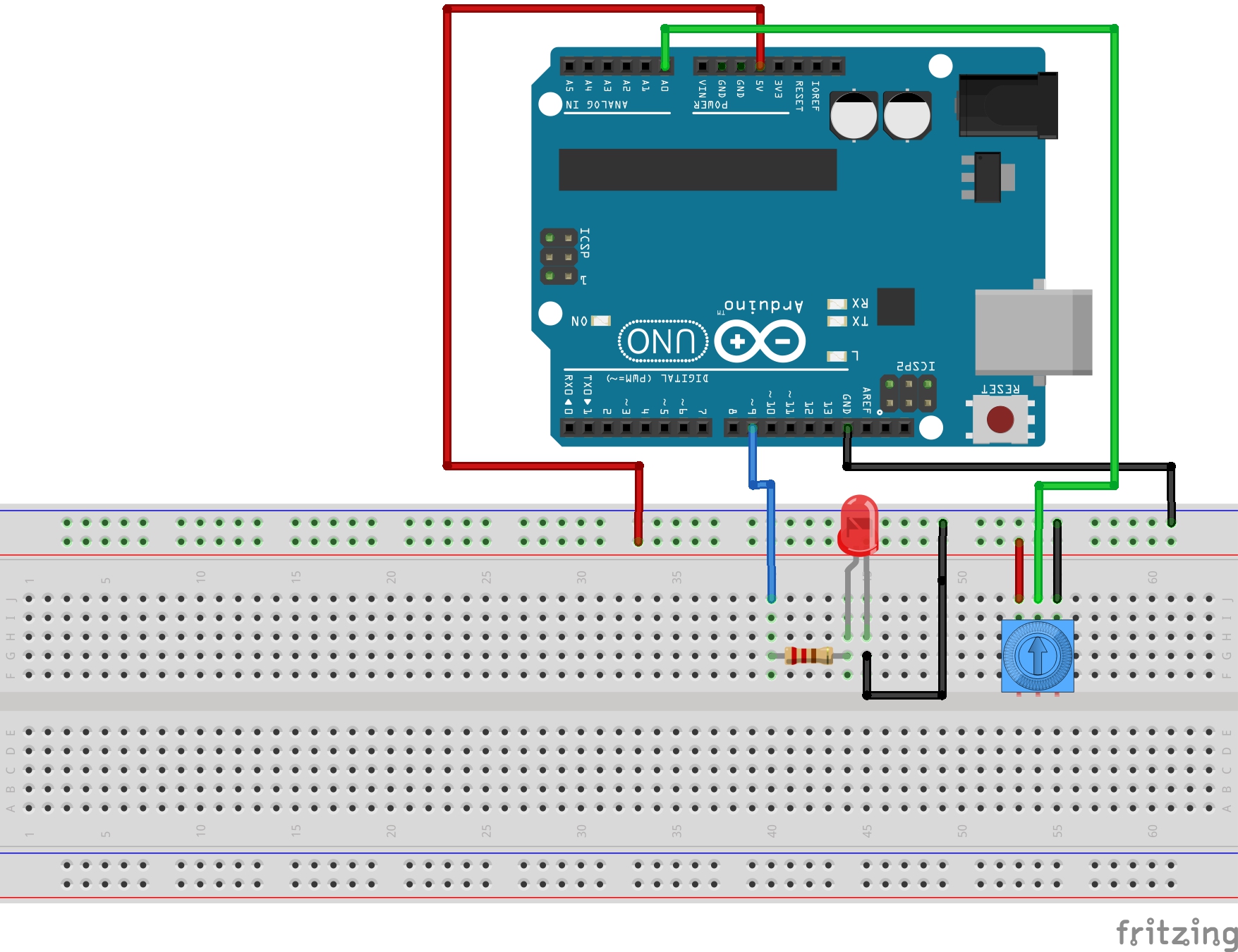
In placing the LED into the circuit, remember that you must always put the longer leg towards the positive voltage. In the case above, the longer leg should be connected to the resistor, and the shorter leg connected to ground. Also remember that we are using a 330 ohm resistor in the circuit to limit the current through the LED.

The goal now is to use what you learned in the last three lessons. You will want to read a value from the potentiometer, and then write a voltage to the LED based on the reading from the potentiometer. Remember that when you read an analog voltage between 0 and 5 volts, the arduino will report a number between 0 and 1023, with 0 representing 0 volts, and 1023 representing 5 volts.

Similarly, when you are writing an analog voltage between 0 and 5 volts, you must write a number between 0 and 255. If you write a “0” value, that corresponds to 0 volts. If you write a value of 255, that will output 5 volts. So, you must scale your write values between 0 and 255 to get voltages between 0 and 5 volts.

The tricky thing now is that we want to dim the LED based on what value we read from the potentiometer. If we read a 0 value from the potentiometer, we want to write a value of 0, which corresponds to a voltage of 0. If we read a value of 1023 from the potentiometer, then we will want to write our maximum voltage of 5 volts, which means we need to write a value of 255. Basically, we need to scale our read values, which will be between 0 and 1023 to suitable write values, which should be between 0 and 255.

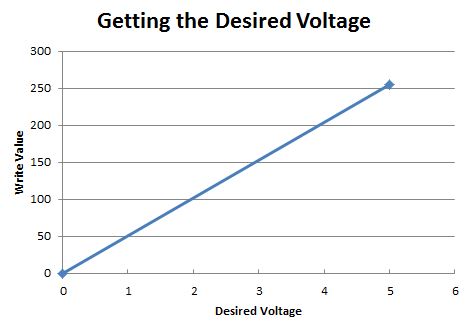
Like in the earlier lessons, this is a simple linear relationship and allows us to use the skills we have learned in math class. This sheet explains the math:

Linear Equation
We must scale our read values (0 to 1023) to suitable write values (0 to 255).

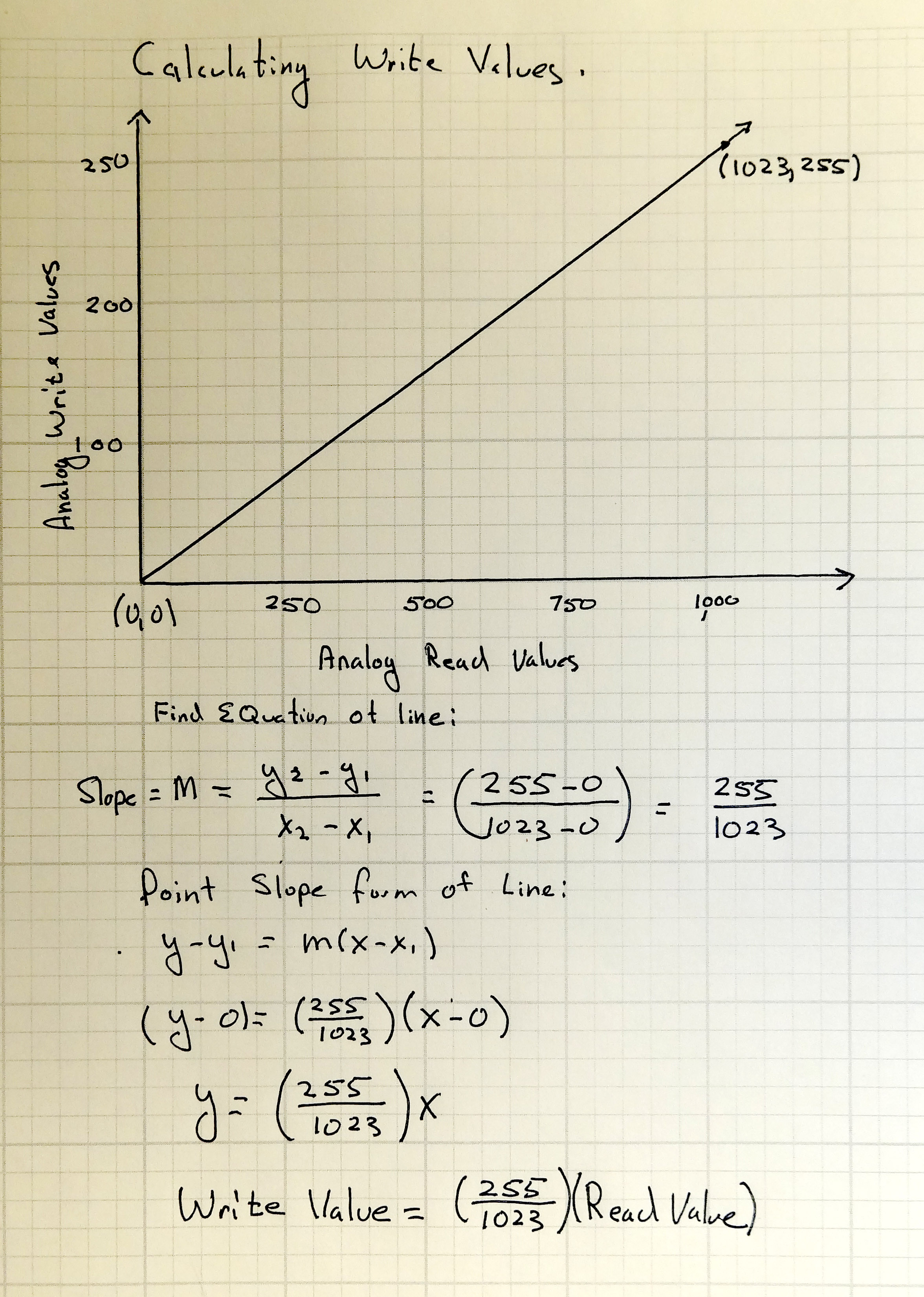
So, from the math above, we can see that the Write Value that we should write to the LED should be the value that we are reading from the potentiometer X (255/1023).

With the math out of the way we can write the program. This code is designed for the schematic above where the potentiometer center leg is read with pin A0 and the LED is written from pin 9.

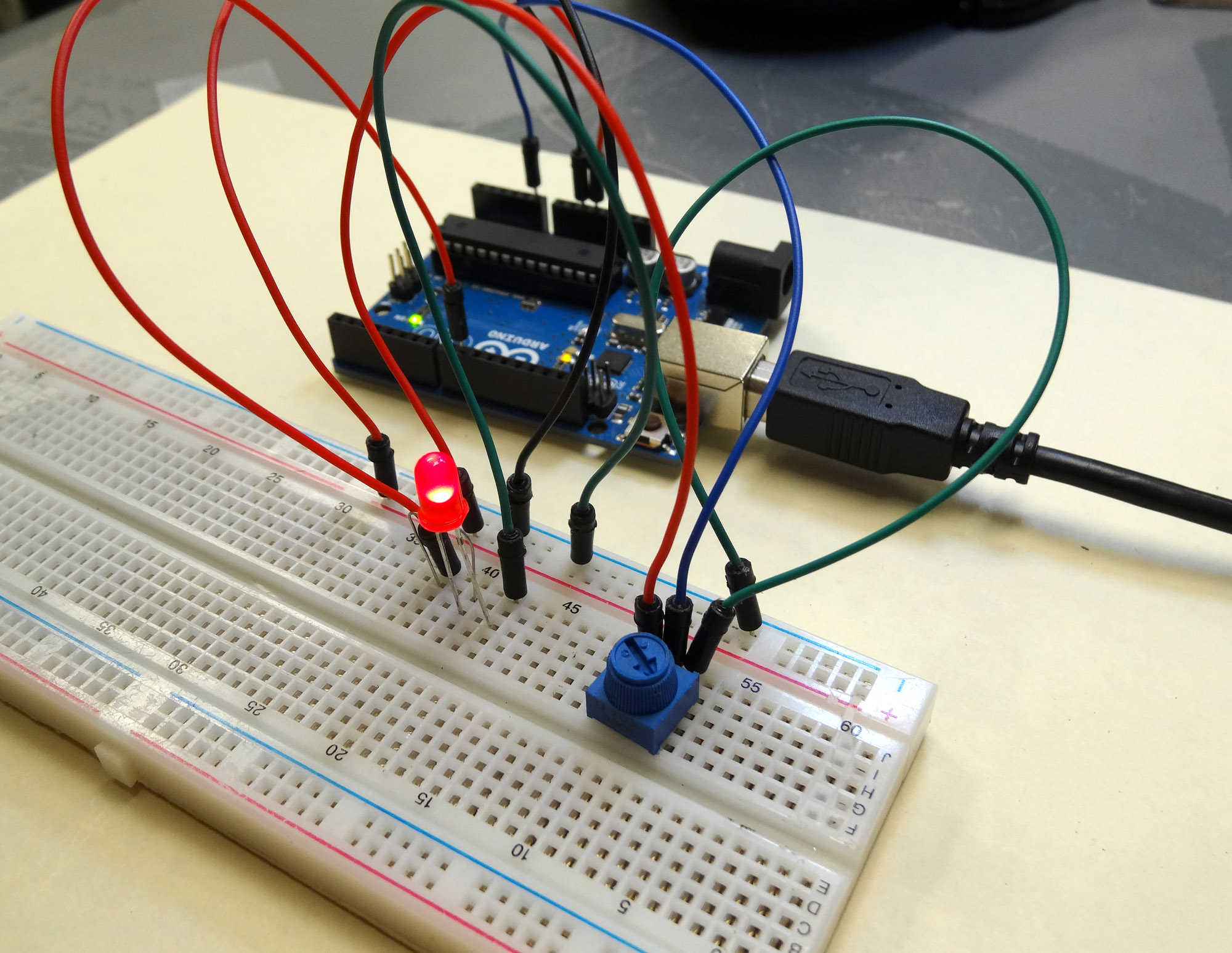
With this code, you should be able to set the brightness from the potentiometer. You read the voltage from the potentiometer and then scale the value you write to the LED based on the reading from the potentiometer.

RESOURCES: On all these lessons I will include resources on where you can purchase the items mentioned in the lecture.

Arduino Microcontroller: You can get a good deal on the arduino on Amazon. Arduinos are open source and many are cheap Chinese knockoffs, so you want to make sure you get an “official” version, which you can at the link above.

Sparkfun Inventor’s Kit: While the bare arduino will get you started, I really suggest getting the Sparkfun Inventor Kit. The projects I will feature in this tutorial set will use the components in this kit, and it is probably cheaper to go ahead and get the kit than to buy the individual components as you go along. The kit is under $100 on Amazon. The sparkfun kits has everything you need including the arduino.

LESSON 10: Analog Reads on the Arduino

In today’s lesson we will learn how to use the analog pins on the arduino to read voltage values from a simple potentiometer circuit. The anolog pins are the pins marked A0 to A5 on the Arduino Uno. These are the pins that can be used for making Analog Voltage measurements.

The circuit we will be using today is a simple voltage divider using a potentiometer. Lesson 9 gives a description of how the potentiometer works.

Potentiometer
This simple circuit allows you to create a voltage divider with a potentiometer


Lesson 8: Writing Analog Voltages in Arduino

We have done some pretty cool stuff so far with the arduino. We have learned how to get input from the user, and how to send information to the user. We have learned how to control commands with both for loops and while loops. We are well on our way to building some really powerful projects. The thing is, so far all of our commands to the arduino pins have in effect been to either turn the pin On or turn it Off. That is, when we digitalWrite HIGH or LOW to the pins, we are either turning on the full 5 volts or turning it all the way off. The truth is that most times we want something in the middle. We would maybe want a voltage of 2.3 volts.

The arduino pins with the squiggly line by them are able to write these in between voltages. These are pins 3,5,6,9,10,11 on the arduino uno.

In the world of engineering and electronics, we say that we want an analog voltage. That is, we want to apply any voltage we want, not just 0 or 5. To output an arbitrary voltage between 0 and 5, would issue the arduino an analogWrite command. Unfortunately, the arguments for the analogWrite command are not as simple as telling it a number between 0 and 5. We must give it an integer between 0 and 255. If we issued the command analogWrite(mypin,0), it would apply 0 volts to mypin. If we issued the command analogWrite(mypin,255), it would appy 5 volts to the pin. As you can see, if we gave the command analogWrite(mypin, 127), we would get about 2.5 volts applied to mypin. You can see those are the easy ones, but in order to figure out exactly what value we should use for exactly the voltage we want, we will need to do some math. Remember all the times you had to calculate the equation of a line in math? Well you are going to do it for real now and for a reason. We need to get an equation that will allow us to calculate the Write Value we should use to get the Voltage

Write Values
You will need to choose the correct value between 0 and 255 to get your desired voltage

You can see that you need the equation for the line above. Good news! You have two points so can calculate the equation of the line. The first point is (0,0), that is to say, that if you want a voltage of 0 to be applied to the pin, you should analogWrite the value of 0, as we explained above. The second point is (5,255), that is to say, if you want to apply a voltage of 5 Volts, you should analogWrite the value 255, as explained above. Now we calculate the equation of the line. the slope would be:

m = (y2-y1)/(x2-x1) = (255-0)/(5-0) = 51

OK, now to get the equation of the line we will use the point slope form of a line, and we get:

(y-y1)=m(x-x1)

We can plug in the point (0,0) and get

(y-0) = m(x – 0)

And when we plug in 51 for m we get:

y = 51X

Remember X is the voltage we want, and Y is the value we write, so this equation can be rewritten:

Write Value = 51 X (Desired Voltage)

So, this equation lets us calculate precisely what value we should analogWrite in order to get the voltage we want on the pin. I hope this makes sense. If you are confused watch the video and it will make more sense.

The bottom line is that we can use this equation to calculate the number we should write to get the voltage that we want at a pin.

As an example, if we wanted to get exactly 2 volts, we should write the value 2X51= 102. If we wanted two volts on the pin myPin, we would issue the command analogWrite(mypin, 102).

Now lets start playing around with a circuit. Lets use the circuit we have been using the last few lessons. Hopefully you still have it hooked up, but if you need help we take you through it step-by-step in Lesson 3.

LED Schematic
This circuit will allow you to independently control two Light Emitting Diodes from the arduino microcontroller

Lets start with our code from Lesson 7:

If you have been following these lessons, this code should make sense as we have built up step by step.

What we need to do now is to replace the four digitalWrite commands with analogWrite commands. Lets say that instead of applying 5 volts to the LED we want to apply 1 volt. This should make the LED’s blink noticeably dimmer. Remember that we would not analogWrite a value of 1, but need to calculate the write value from our formula. We want a voltage of 1 volt, so our write value should be 1 X 51, or the value 51. So now instead of digitalWrite, we should have a command like analogWrite(redLEDPin, 51) or analogWrite(yellowLEDPin, 51). Notice that on the commands that turn the LEDs off . . . digitalWrite(redLEDPin, LOW) would still work to turn the pins off, but I think it is good practice to change all the writes to analogWrites in a problem like this. To turn the pin off with an analog write would could use the command analogWrite(redLEDPin, 0).

With this new knowledge, you should modify your code and replace the 4 digitalWrite commands with analogWrite commands. Play around with writing different values to see the effect on the LED Brightness.

Arduino Lesson 7: Using While Loops

In Lesson 3 we learned how to use for loops. For loops are very powerful and they are sufficient to take care of most of your looping needs. However, there is another type of loop called a ‘while loop’.  The while loop is not better than a for loop, it is just a different way of looping. In most scenarios you could choose to loop with either a for loop or a while loop. In lesson 6 we briefly introduced while loops, and used one to pause the program to wain on user input. In this lesson we will look in more detail at how while loops work. We will continue to work with this circuit, which you first built in lesson 3. If you need help putting it together go back and see Lesson 3.

LED Schematic
This circuit will allow you to independently control two Light Emitting Diodes from the arduino microcontroller

Also, we will continue to expand the code we developed in Lesson 6. At the end of Lesson 6, our code looked something like this:

You can see in the code above, we are prompting the user for data, then waiting, then entering the data for both numRedBlinks and numYellowBlinks. This allows the user to set the number of times the LED’s blink from the serial monitor. The way we actually do the blinking is with the two for loops. There is another way to loop, and that is with ‘while loops’. When you are writing code, often times you can choose a for loop or a while loop. Some people frequently use both types of loops and some have a preference for one or the other and almost always use their preferred type of loop. It is good to know how to use both types, so here we will explore the while loop.

Lets look at how one might work:

 Lets unpack this code and see how it works. First, notice that the while loop will have one or more commands that it executes. It will execute the commands that are between the curly brackets.  It will continue to execute the commands between the curly brackets as long as the ‘condition’ described in the parenthesis of the while loop is true. In the case above, it will continue to execute the commands between the curly brackets as long as j is less than or equal to ten. notice that inside the loop we are incrementing j by 1 each time through the loop. This ensures that it will eventually exit the loop. If we were to forget to increment j, the program would become hung in the loop. This would create what is called an infinite loop, and the program would become hung in the infinite loop.

So, for the code above, we start by making j=1, then each time through the loop we increment j by 1. The program will continue executing this loop until the condition is no longer true . . . for this case, at the point that j=11 the condition would no longer be true, the program would not enter the curly bracket, and would jump to the first line of code after the closing curly bracket.

So, for this lesson what we want to do is replace the for loops in the original code shown at the top of this lesson with while loops. There is one for loop that blinks the red LED and one for loop that blinks the yellow LED. Replace those two for loops with while loops. Lets look at the first for loop again:

Lets do the same function with a while loop. We could replace this code with: