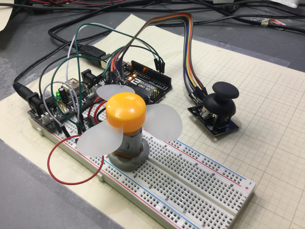
This is the arduino code we developed in this lesson to approximate roll, pitch and yaw over small ranges.
1 2 3 4 5 6 7 8 9 10 11 12 13 14 15 16 17 18 19 20 21 22 23 24 25 26 27 28 29 30 31 32 33 34 35 36 37 38 39 40 41 42 43 44 45 46 47 48 49 50 51 52 53 54 55 56 57 58 59 60 61 62 63 64 65 66 67 68 69 70 71 72 73 74 75 76 77 78 79 80 81 82 83 84 85 86 87 88 89 90 91 | #include <Wire.h> #include <Adafruit_Sensor.h> #include <Adafruit_BNO055.h> #include <utility/imumaths.h> #include <math.h> float thetaM; float phiM; float thetaFold=0; float thetaFnew; float phiFold=0; float phiFnew; float thetaG=0; float phiG=0; float theta; float phi; float thetaRad; float phiRad; float Xm; float Ym; float psi; float dt; unsigned long millisOld; #define BNO055_SAMPLERATE_DELAY_MS (100) Adafruit_BNO055 myIMU = Adafruit_BNO055(); void setup() { // put your setup code here, to run once: Serial.begin(115200); myIMU.begin(); delay(1000); int8_t temp=myIMU.getTemp(); myIMU.setExtCrystalUse(true); millisOld=millis(); } void loop() { // put your main code here, to run repeatedly: uint8_t system, gyro, accel, mg = 0; myIMU.getCalibration(&system, &gyro, &accel, &mg); imu::Vector<3> acc =myIMU.getVector(Adafruit_BNO055::VECTOR_ACCELEROMETER); imu::Vector<3> gyr =myIMU.getVector(Adafruit_BNO055::VECTOR_GYROSCOPE); imu::Vector<3> mag =myIMU.getVector(Adafruit_BNO055::VECTOR_MAGNETOMETER); thetaM=-atan2(acc.x()/9.8,acc.z()/9.8)/2/3.141592654*360; phiM=-atan2(acc.y()/9.8,acc.z()/9.8)/2/3.141592654*360; phiFnew=.95*phiFold+.05*phiM; thetaFnew=.95*thetaFold+.05*thetaM; dt=(millis()-millisOld)/1000.; millisOld=millis(); theta=(theta+gyr.y()*dt)*.95+thetaM*.05; phi=(phi-gyr.x()*dt)*.95+ phiM*.05; thetaG=thetaG+gyr.y()*dt; phiG=phiG-gyr.x()*dt; phiRad=phi/360*(2*3.14); thetaRad=theta/360*(2*3.14); Xm=mag.x()*cos(thetaRad)-mag.y()*sin(phiRad)*sin(thetaRad)+mag.z()*cos(phiRad)*sin(thetaRad); Ym=mag.y()*cos(phiRad)+mag.z()*sin(phiRad); psi=atan2(Ym,Xm)/(2*3.14)*360; Serial.print(phi); Serial.print(","); Serial.print(theta); Serial.print(","); Serial.print(psi); Serial.print(","); Serial.print(accel); Serial.print(","); Serial.print(gyro); Serial.print(","); Serial.print(mg); Serial.print(","); Serial.println(system); phiFold=phiFnew; thetaFold=thetaFnew; delay(BNO055_SAMPLERATE_DELAY_MS); } |
This is the python code we developed to visualize the 3 dimensional rotation of a rigid body.
1 2 3 4 5 6 7 8 9 10 11 12 13 14 15 16 17 18 19 20 21 22 23 24 25 26 27 28 29 30 31 32 33 34 35 36 37 38 39 40 41 42 43 44 45 46 47 48 49 50 51 52 53 54 | from vpython import * from time import * import numpy as np import math import serial ad=serial.Serial('com5',115200) sleep(1) scene.range=5 toRad=2*np.pi/360 toDeg=1/toRad scene.forward=vector(-1,-1,-1) scene.width=600 scene.height=600 xarrow=arrow(lenght=2, shaftwidth=.1, color=color.red,axis=vector(1,0,0)) yarrow=arrow(lenght=2, shaftwidth=.1, color=color.green,axis=vector(0,1,0)) zarrow=arrow(lenght=4, shaftwidth=.1, color=color.blue,axis=vector(0,0,1)) frontArrow=arrow(length=4,shaftwidth=.1,color=color.purple,axis=vector(1,0,0)) upArrow=arrow(length=1,shaftwidth=.1,color=color.magenta,axis=vector(0,1,0)) sideArrow=arrow(length=2,shaftwidth=.1,color=color.orange,axis=vector(0,0,1)) bBoard=box(length=6,width=2,height=.2,opacity=.8,pos=vector(0,0,0,)) bn=box(length=1,width=.75,height=.1, pos=vector(-.5,.1+.05,0),color=color.blue) nano=box(lenght=1.75,width=.6,height=.1,pos=vector(-2,.1+.05,0),color=color.green) myObj=compound([bBoard,bn,nano]) while (True): while (ad.inWaiting()==0): pass dataPacket=ad.readline() dataPacket=str(dataPacket,'utf-8') splitPacket=dataPacket.split(",") roll=float(splitPacket[0])*toRad pitch=float(splitPacket[1])*toRad yaw=float(splitPacket[2])*toRad+np.pi print("Roll=",roll*toDeg," Pitch=",pitch*toDeg,"Yaw=",yaw*toDeg) rate(50) k=vector(cos(yaw)*cos(pitch), sin(pitch),sin(yaw)*cos(pitch)) y=vector(0,1,0) s=cross(k,y) v=cross(s,k) vrot=v*cos(roll)+cross(k,v)*sin(roll) frontArrow.axis=k sideArrow.axis=cross(k,vrot) upArrow.axis=vrot myObj.axis=k myObj.up=vrot sideArrow.length=2 frontArrow.length=4 upArrow.length=1 |