In this lesson we explore use of the HC-SR04 sensor to measure the speed of sound. The hookup and programming are pretty simple. The Elegoo Kit includes this sensor, so if you have the kit, you will be using the same hardware we are using. This project builds on the work we did in Lesson 53.
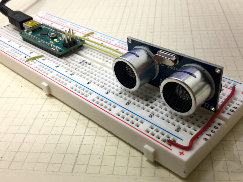
For this build we will be using an Arduino Nano, which allows the project to be built on a single breadboard. This allows cleaner build, and one less likely to have problems from intermittent connections. The build neatness is also facilitated by using small straight jumper wires, which you can get HERE.
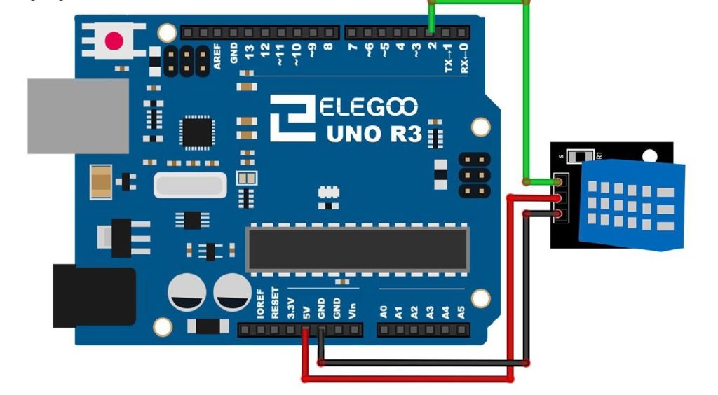
You can connect the sensor up according to this schematic:
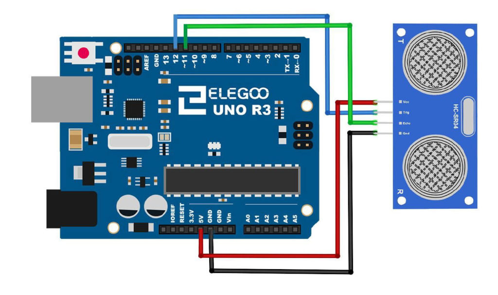
The connection pins are the same when connecting to a Nano.
The video below explains how to measure speed of sound from data coming from this sensor.
Code used in Today’s Lesson:
|
1 2 3 4 5 6 7 8 9 10 11 12 13 14 15 16 17 18 19 20 21 |
int trigPin=12; int echoPin=11; int pingTravelTime; void setup() { // put your setup code here, to run once: pinMode(trigPin,OUTPUT); pinMode(echoPin,INPUT); Serial.begin(9600); } void loop() { // put your main code here, to run repeatedly: digitalWrite(trigPin,LOW); delayMicroseconds(10); digitalWrite(trigPin,HIGH); delayMicroseconds(10); digitalWrite(trigPin,LOW); pingTravelTime=pulseIn(echoPin,HIGH); delay(25); Serial.println(pingTravelTime); } |