Arduino Tutorial 54: Measuring Speed of Sound With HC-SR04 Sensor

HC-SR04
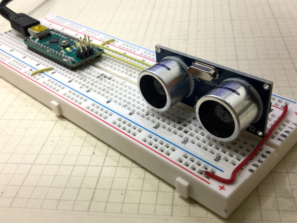
This is our HC-SR04 Ultrasonic Sensor Connected to our Arduino Nano.

In this lesson we explore use of the HC-SR04 sensor to measure the speed of sound. The hookup and programming are pretty simple. The Elegoo Kit includes this sensor, so if you have the kit, you will be using the same hardware we are using. This project builds on the work we did in Lesson 53.

For this build we will be using an Arduino Nano, which allows the project to be built on a single breadboard. This allows cleaner build, and one less likely to have problems from intermittent  connections. The build neatness is also facilitated by using small straight jumper wires, which you can get HERE.

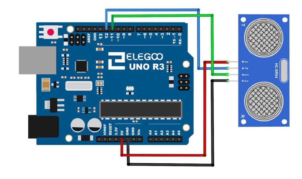
You can connect the sensor up according to this schematic:
HC-SR04-Schematic
Schematic for Connecting the HC-SR04 to an Arduino

The connection pins are the same when connecting to a Nano.

The video below explains how to measure speed of sound from data coming from this sensor.

Code used in Today’s Lesson:


Arduino Tutorial 53: Understanding and Connecting the HC-SR04 Sensor

HC-SR04
This is our HC-SR04 Ultrasonic Sensor Connected to our Arduino Nano.

In this lesson we explore using the HC-SR04 sensor. The sensor sends out a ping, and then waits to hear the echo. It measures the time between when the ping is sent and when the echo is heard. Knowing pingTravelTime, allows you to calculate distance from the sensor. In this lesson we will show you how to connect the sensor, and program it to read pingTravelTime. In future lessons we will show you how to change this into distance.

Notice we used an Arduino Nano, which allows the entire project to be build on a single breadboard. This allows a neater, smaller build, and one less likely to have problems from poor or loose connections. The build neatness is also facilitated by using small straight jumper wires, which you can get HERE.

Connecting up the HC-SR04 sensor is simple, as illustrated in this diagram:

HC-SR04-Schematic
Schematic for Connecting the HC-SR04 to an Arduino

This video will take you through our build and initial work step-by-step.

The simple code below is what we used in the video to begin making measurements with the sensor.


Arduino Tutorial 52: Portable Temperature and Humidity Sensor with DHT11

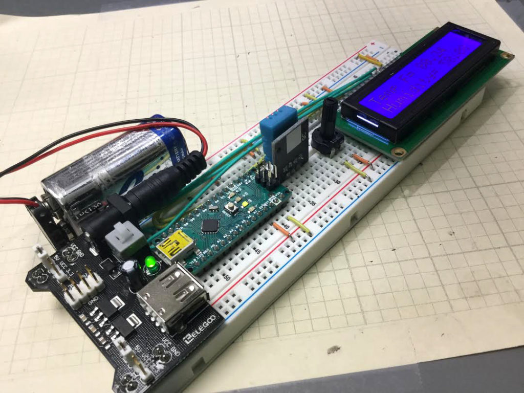
portable temperature sensor
This shows our completed build creating a completely portable DHT11 sensor system

In this lesson we build a completely portable Temperature and Humidity Sensor using the DHT11 sensor. The project is powered by a 9 Volt battery, through the power supply board supplied in the Elegoo Kit.  This project builds on the work we did in Lessons 50 and 51.

Also, notice we used an Arduino Nano, which allows the entire project to be build on a single breadboard. This allows a neater, smaller build, and one less likely to have problems from poor or loose connections. The build neatness is also facilitated by using small straight jumper wires, which you can get HERE.

In the configuration in this project, the regulated power supply is providing power to the Arduino through the 5 Volt pin. In such cases, you should not Also plug the USB cable into the arduino. When powering the Arduino with a regulated power supply, do not connect the USB. If you need to program the arduino, disconnect the external power supply first.

The video below gives a detailed step-by-step description of the project.


The code we developed is presented below:


AI ON THE JETSON NANO LESSON 28: Tracking Objects in OpenCV using Contours


In Lesson 27 we learned how to isolate an object of interest by masking it, and separating it from the background. In this lesson we learn how to track the object of interest by creating OpenCV contours, and then drawing a con tour or box around the object of interest in the original frame. This allows us to track objects of interest in real time on live videos. The video above takes you through the lesson step-by-step, and below is the demo code we developed during the lesson


AI ON THE JETSON NANO LESSON 29: Gear to Create a Pan Tilt Camera Platform for Real Time Tracking

Now that we are able to isolate and track objects using the Jetson Nano and OpenCV, now we can create a pan tilt platform for the camera, so the camera can actually track and follow the object of interest in the scene.  We will do this be using two servos and then some mounting brackets. Below, I show the gear you will need to order to continue.

First we will need to be able to mount our camera on the pan/tilt bracket. If you have the Logitech WEB cam, then it can be affixed to the bracket in any number of different ways. I you are using the Raspberry Pi camera, you will need to either pick up the Logitech WEB cam, or you will need a longer cable for the Raspberry Pi Camera. For this project, I prefer the logitech WEB cam. But if price is a barrier, the simplest solution is to order the set of longer cables. You can get this gear from these links:

Logitech WEB cam

Raspberry Pi Long Camera Cable Set

Now you will need a couple of good servos to drive the pan tilt brackets. I found this set works well, and the price is good, and you will end up with a couple of spares, which is always useful.

Servo Set

You will also need a pan/tilt bracket for the servos and cameras, and the one below is the set I am using in this project.

Pan/Tilt Camera Bracket Set

And Finally you will need an PCA9685 I2C Servo Control Board. You can pick up what you need here:

Servo Control Board

The link above is for a pair of the boards,  and you only need one. I suggest getting the pair so you have a spare if needed, or it can be used for other projects. And that is all you will need!

Making The World a Better Place One High Tech Project at a Time. Enjoy!