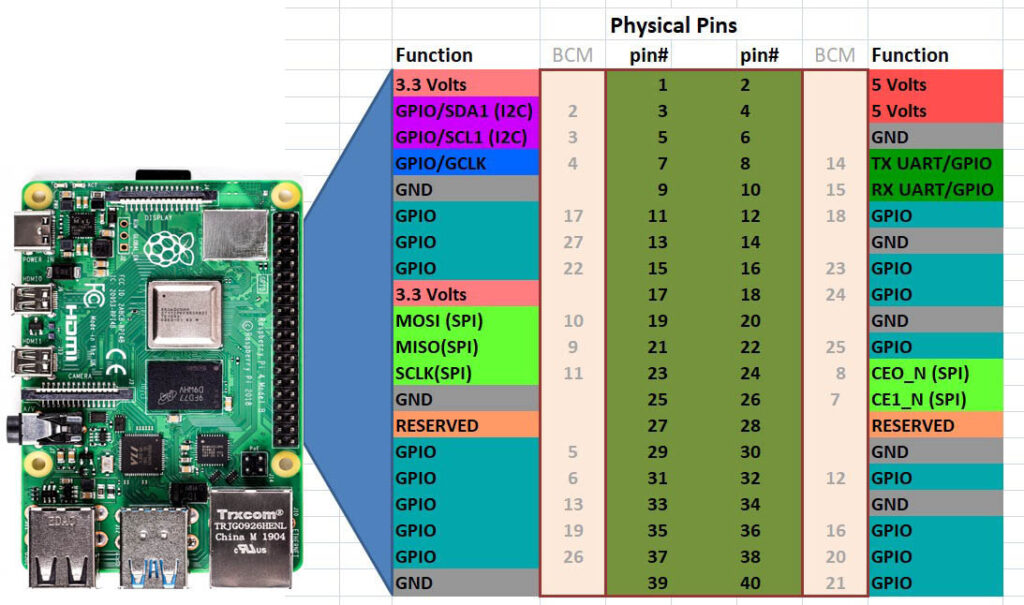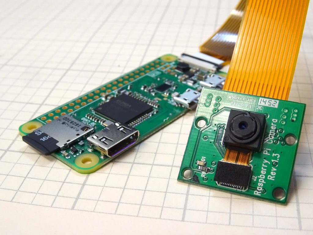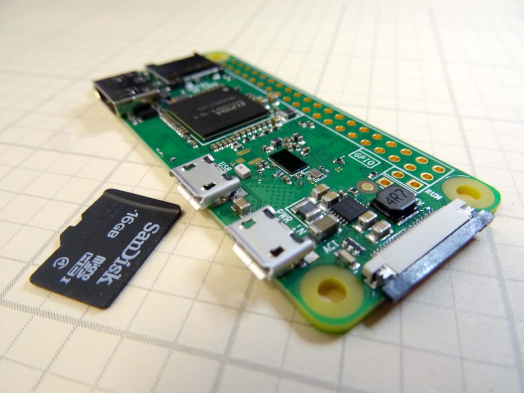
Unfortunately the Raspberry Pi has no built in Analog to Digital converters for reading analog voltage values. So, what was a very easy task on the arduino becomes a more difficult task on the Pi. However, many applications and projects on the pi require reading analog values. In order to do this, we must interface to a ADC0834 Analog to Digital Converter chip. The video above provides in depth description of how to do this, but the resources below should also help you.
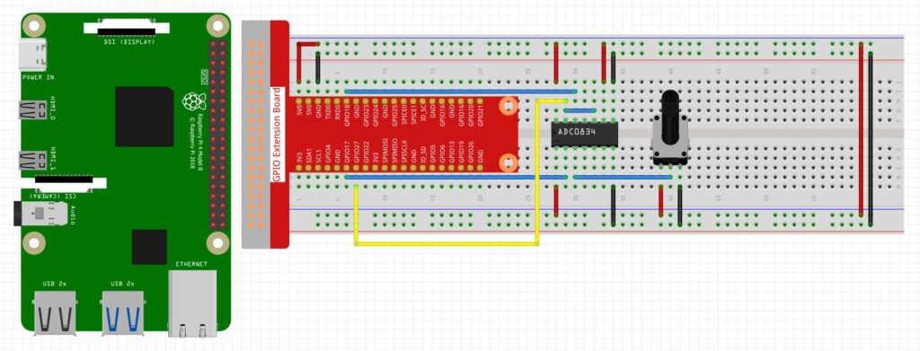
You can click on the image for a closer view of the diagram.
In order to use the chip, you will need to install a python library on the raspberry pi. Create a python file on your raspberry pi, and name it:
ADC0834.py
You must name it exactly that. Note the 0 in the above file name is a zero. Now copy and paste the following code into the file:
|
1 2 3 4 5 6 7 8 9 10 11 12 13 14 15 16 17 18 19 20 21 22 23 24 25 26 27 28 29 30 31 32 33 34 35 36 37 38 39 40 41 42 43 44 45 46 47 48 49 50 51 52 53 54 55 56 57 58 59 60 61 62 63 64 65 66 67 68 69 70 71 72 73 74 75 76 77 78 79 80 81 82 83 84 85 86 87 88 89 90 91 92 93 94 95 96 97 98 99 100 101 102 103 104 105 106 107 108 109 110 111 112 113 114 115 116 117 118 119 120 121 122 123 124 125 126 127 |
#!/usr/bin/env python3 #----------------------------------------------------- # # This is a program for all ADC chip. It # convert analog singnal to digital signal. # # This program is most analog signal modules' # dependency. Use it like this: # `import ADC0834` # `sig = ADC0834.getResult(chn)` # # *'chn' should be 0,1,2,3 represent for ch0, ch1, ch2, ch3 # on ADC0834 # import RPi.GPIO as GPIO import time ADC_CS = 17 ADC_CLK = 18 ADC_DIO = 27 # using default pins for backwards compatibility def setup(cs=17,clk=18,dio=27): global ADC_CS, ADC_CLK, ADC_DIO ADC_CS=cs ADC_CLK=clk ADC_DIO=dio GPIO.setwarnings(False) GPIO.setmode(GPIO.BCM) # Number GPIOs by BCM mode GPIO.setup(ADC_CS, GPIO.OUT) # Set pins' mode is output GPIO.setup(ADC_CLK, GPIO.OUT) # Set pins' mode is output def destroy(): GPIO.cleanup() # using channel = 0 as default for backwards compatibility def getResult(channel=0): # Get ADC result, input channel sel = int(channel > 1 & 1) odd = channel & 1 # print("sel: {}, odd: {}".format(sel, odd)) GPIO.setup(ADC_DIO, GPIO.OUT) GPIO.output(ADC_CS, 0) # Start bit GPIO.output(ADC_CLK, 0) GPIO.output(ADC_DIO, 1) time.sleep(0.000002) GPIO.output(ADC_CLK, 1) time.sleep(0.000002) # Single End mode GPIO.output(ADC_CLK, 0) GPIO.output(ADC_DIO, 1) time.sleep(0.000002) GPIO.output(ADC_CLK, 1) time.sleep(0.000002) # ODD GPIO.output(ADC_CLK, 0) GPIO.output(ADC_DIO, odd) time.sleep(0.000002) GPIO.output(ADC_CLK, 1) time.sleep(0.000002) # Select GPIO.output(ADC_CLK, 0) GPIO.output(ADC_DIO, sel) time.sleep(0.000002) GPIO.output(ADC_CLK, 1) time.sleep(0.000002) GPIO.output(ADC_CLK, 0) time.sleep(0.000002) # ODD # GPIO.output(ADC_CLK, 0) # GPIO.output(ADC_DIO, channel) # time.sleep(0.000002) # GPIO.output(ADC_CLK, 1) # GPIO.output(ADC_DIO, 1) # time.sleep(0.000002) # GPIO.output(ADC_CLK, 0) # GPIO.output(ADC_DIO, 1) # time.sleep(0.000002) dat1 = 0 for i in range(0, 8): GPIO.output(ADC_CLK, 1); time.sleep(0.000002) GPIO.output(ADC_CLK, 0); time.sleep(0.000002) GPIO.setup(ADC_DIO, GPIO.IN) dat1 = dat1 << 1 | GPIO.input(ADC_DIO) dat2 = 0 for i in range(0, 8): dat2 = dat2 | GPIO.input(ADC_DIO) << i GPIO.output(ADC_CLK, 1); time.sleep(0.000002) GPIO.output(ADC_CLK, 0); time.sleep(0.000002) GPIO.output(ADC_CS, 1) GPIO.setup(ADC_DIO, GPIO.OUT) if dat1 == dat2: return dat1 else: return 0 def getResult1(): return getResult(1) def loop(): while True: for i in range(4): res = getResult(i) print ('res{} = {}'.format(i,res)) time.sleep(0.1) time.sleep(1) if __name__ == '__main__': # Program start from here setup() try: loop() except KeyboardInterrupt: # When 'Ctrl+C' is pressed, the child program destroy() will be executed. destroy() |
This file, ADC0834.py, should then be put in the following directory:
/usr/lib/python3.7/
Moving or copying the file to that directory might require use of Sudo if you get a permissions error.
Now the following code will allow you to read the analog value coming from the potentiometer in the above circuit diagram:
|
1 2 3 4 5 6 7 8 9 10 11 12 13 14 15 |
import RPi.GPIO as GPIO import ADC0834 import time GPIO.setmode(GPIO.BCM) ADC0834.setup() try: while True: analogVal=ADC0834.getResult(0) print(analogVal) time.sleep(.2) except KeyboardInterrupt: GPIO.cleanup() print('GPIO Good to Go') |