Tag Archives: High School Science

LESSON 13: Controlling RGB LED with Arduino

OK, we are ready to move forward and learn new circuit skills and new programming skills. In today’s lesson we will learn how to control an RGB (Red, Green, Blue) LED with an arduino microcontroller! This will introduce us to a new circuit component, and will require us to learn some new programming skills.

RGB LED
Circuit to control RGB LED with an Arduino

An RGB LED is basically three LED’s in one. It has 4 leads. One lead, the long lead, is the common ground. Then one lead controls the red LED, one lead controls the green LED, and one lead controls the blue LED. All three of the LED’s are connected to ground through the same pin. You can control the color you get out of the LED based on the voltages you write to the different control pins. A schematic will probably help you understand how the component works and how you should hook up to it.

RGB LED
This schematic shows how to work with a common cathode RGB LED

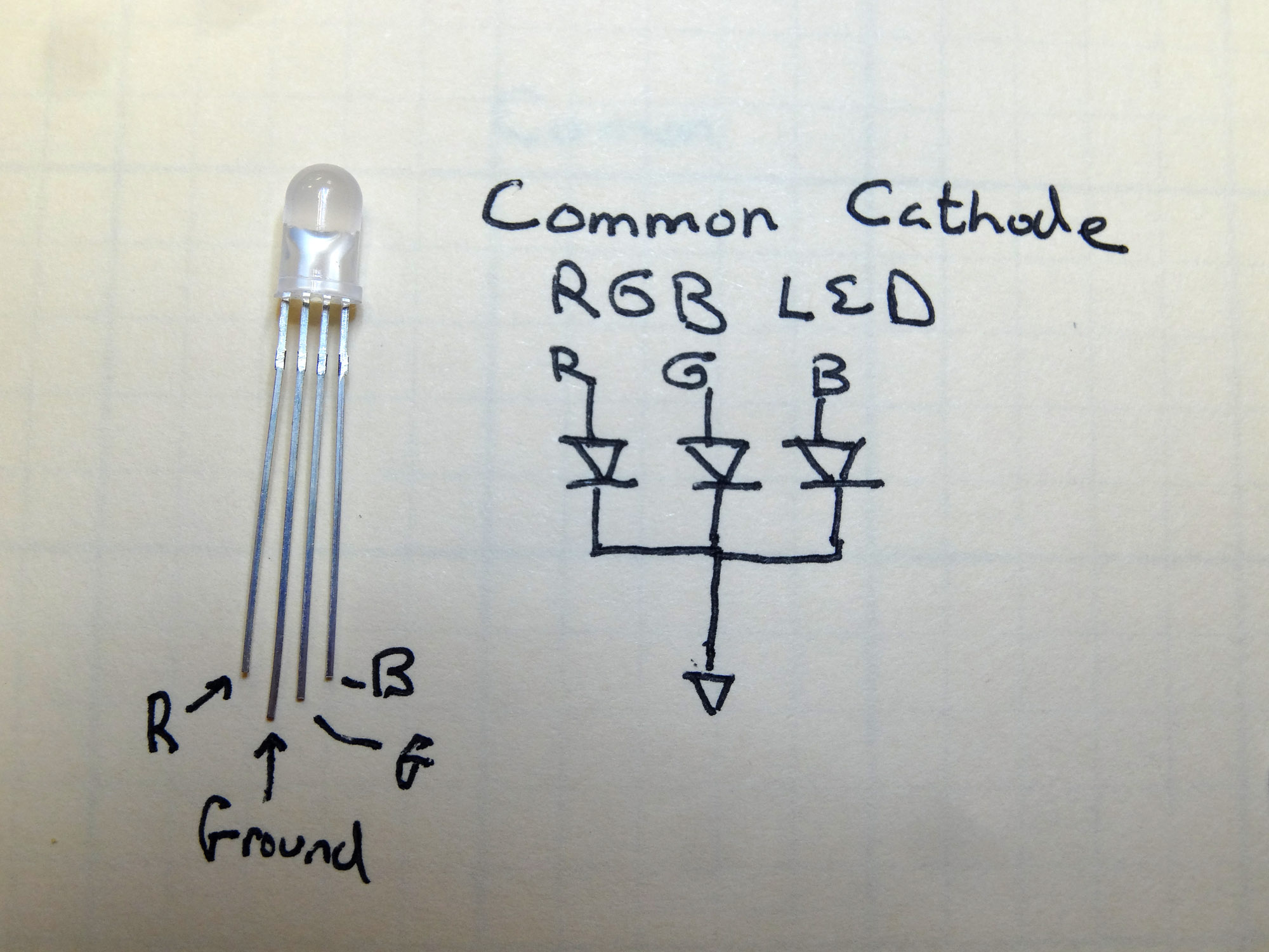
This picture shows the four pins for a common cathode RGB LED. “Common Cathode” just means that the LED’s share the ground pin. There are also “Common Anode” LED’s which share a common high voltage pin, and then each color has its own ground. I think these are much more confusing, but just mention them so that you know that this tutorial is for the common cathode type.  The Sparkfun Inventor Kit has the common cathode configuration, which is the type I prefer. Also note in the drawing you can see that the length of the pins is your clue as to which pin controls red, which green and which blue.

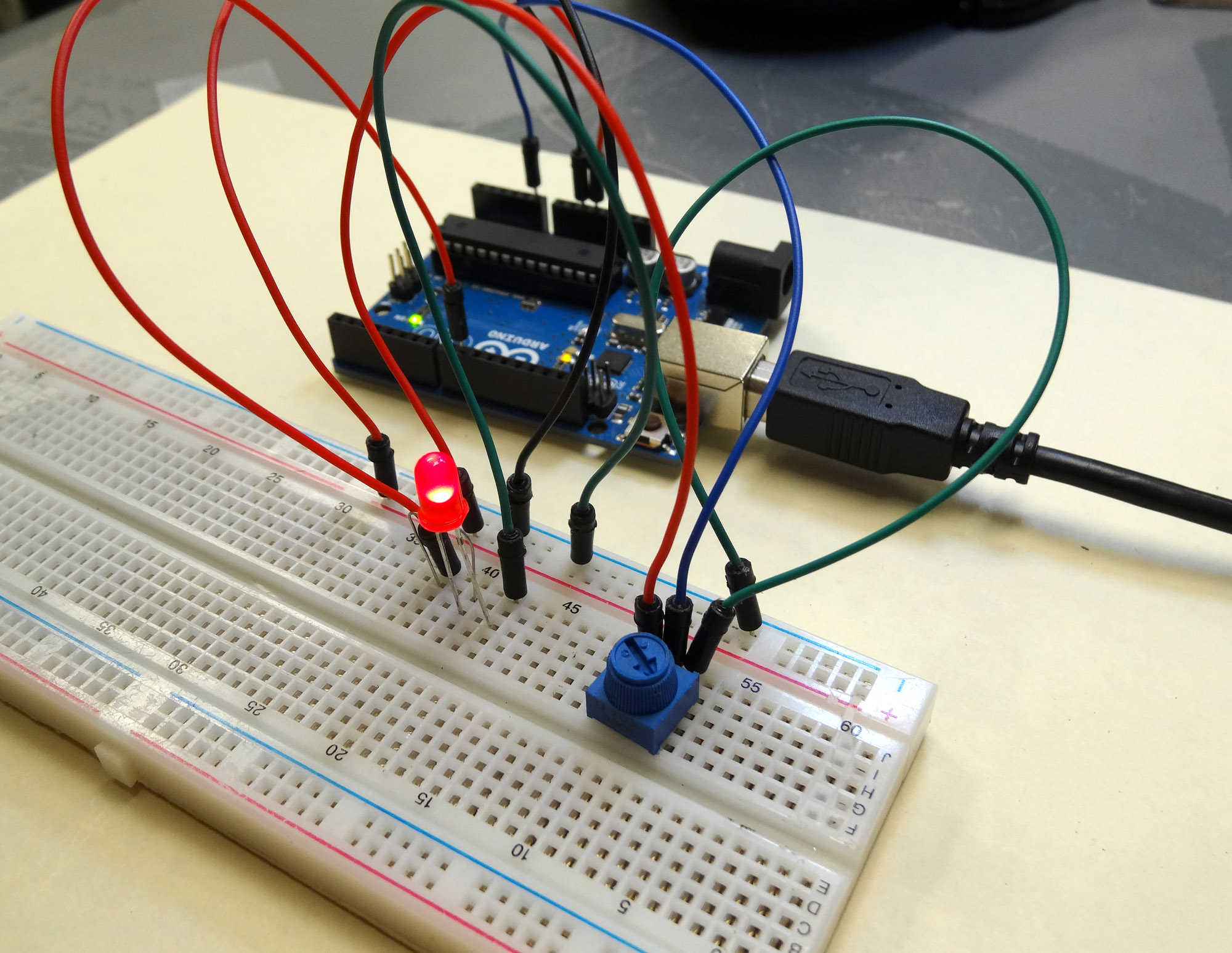
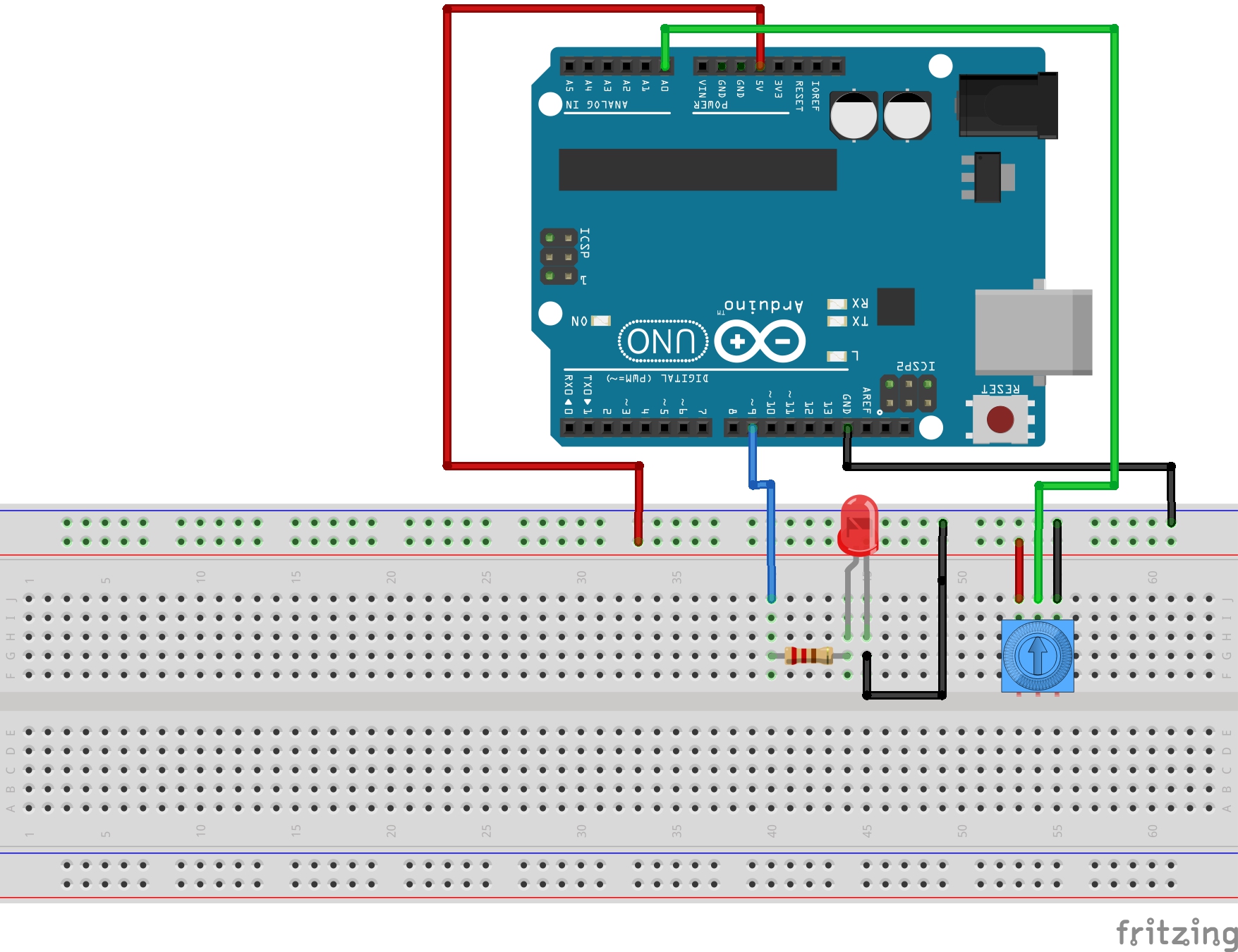
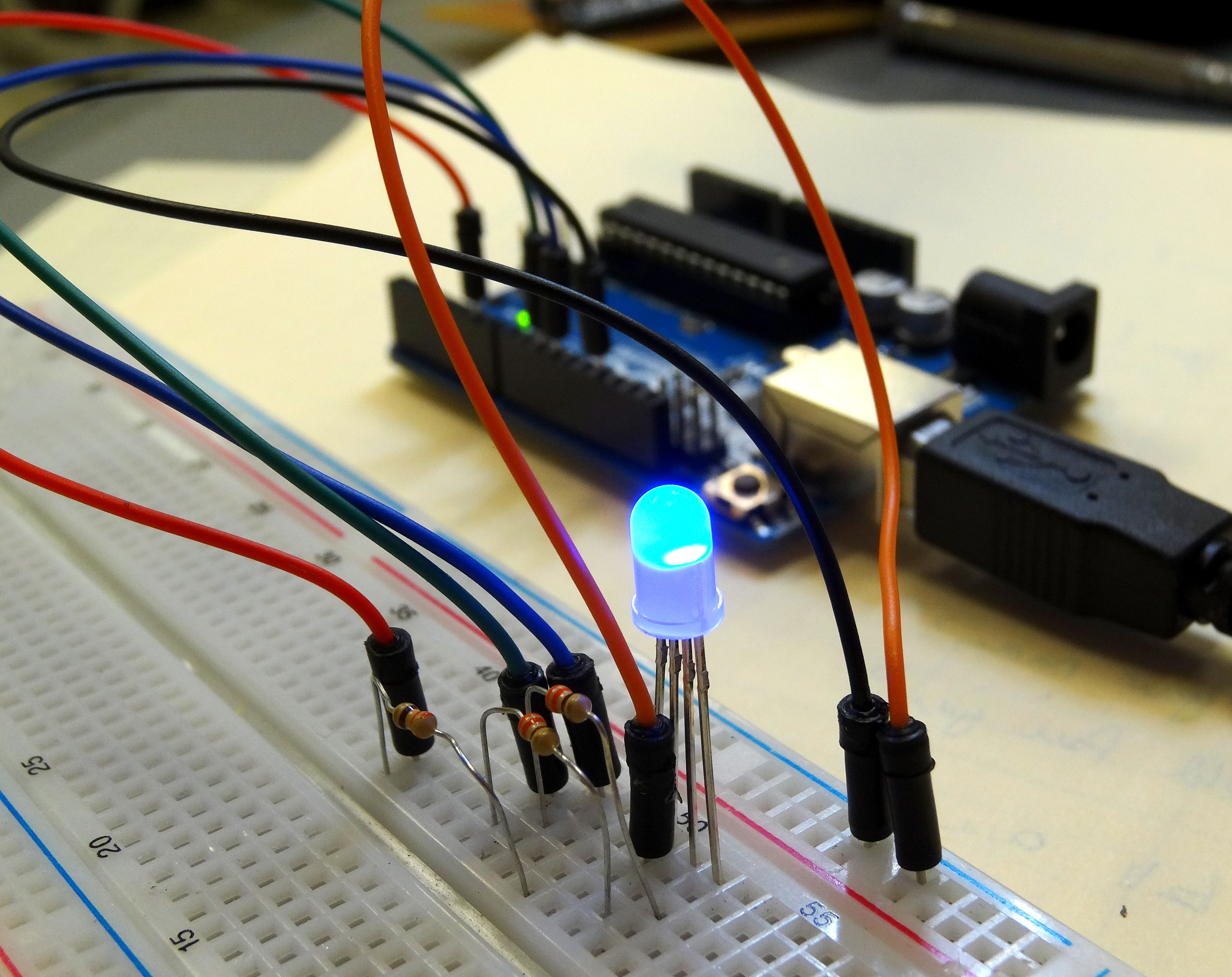
Now lets think about using this in a circuit. As you can see in the schematic, all three of the LED’s share a common ground pin. You can easily see that pin should be connected to your circuit ground. Now, think about how you would connect the control pins. To control a normal LED, you needed to connect to one arduino output pin. To control this LED, how many control pins will you need to use on the arduino? That’s right . . . you will need three control pins. Also, remember than you never connect an LED directly to a voltage source, you always use a series current limiting resistor (typically 330 ohms). For these new RGB LED’s how many current limiting resistors will we need? We will need three . . . each color control pin will need its own current limiting resistor. So each color control pin will connect to an arduino output pin through its own current limiting resistor. Once that is hooked up, we can control what color the LED is by writing voltages from the arduino to specific legs of the RGB LED. If we write a voltage to the red pin, the LED will be red. If we write a voltage to the blue pin, the LED will be blue. Also the exciting thing is that if you write voltages to multiple pins, you can get the in between blended colors. Basically by analogWrite-ing different values to the 3 different control pins, you can get any imaginable color. But first, lets go ahead and get our circuit set up. The following schematic controls red from arduino pin 6, green from arduino pin 10 and blue from arduino pin 11. Go ahead and hook this circuit up.

Arduino RGB LED circuit
Arduino circuit to control the color of an RGB LED.

Now lets play around with a program that will independently turn on the different colors. We will start simple so we can get an intuitive feel for how the LED works.

 With the code above, what color do you anticipate the LED will be? Hook up the circuit and type in the code, and see what happens. It is important that you type in the code. Do not cut and paste my code. You need to type it in. When you type it in, you will probably make mistakes and when you do you will have to troubleshoot or debug your code. That means you have to find your mistakes. All programmers make mistakes, and it is important very early on to learn how to find your mistakes.

Modify the code above so that the LED turns green.

Now modify it again so that the LED turns red.

Now try for the in between colors. How would you get the LED to turn orange? Play around with achieving different colors. Try to get the following colors:

Cyan

Magenta

Yellow

Orange

Purple

LESSON 12: Simple and Easy Way to Read Strings, Int’s and float’s Over Arduino Serial Port

One of my biggest frustrations in programming is the confusion over inputting data over the serial port. There are lots of Arduino tutorials that make it much harder than it has to be. There are many difficult and complicated ways you can read data over the serial port, but luckily there is an easy way. While we touched on this briefly in earlier videos, it is such an important topic I want to focus on it in this lesson.

In order to read data over the serial port,  you first have to determine what type of data you will be expecting. Almost all possible needs can be covered by three simple data types. Usually you can make just about any project work with Strings, Float’s, or Int’s. So, you need to know how to read these three data types over the serial port. The easiest way to read a string of text is using the Serial.readString() command. The easiest way to read a Float is with the Serial.parseFloat() command and the easiest way to read in Int with with the Serial.parseInt() command.

To practice this, lets do the following. Write a program that will promt the user for his age, for how much he weighs, and then how tall he is in feet. Then print out a nicely formatted output that relays that information back to the user.

In order to do this the first thing we must do is decide what type of variables to use for each of these three pieces of data.  For the person’s name, you naturally would use a String, since a name is a string of text. To store the weight, we would just about always round to the nearest whole number so it would make sense to use an Int for this. On height, we would not normally round to the nearest foot . . . we might want to say that someone was 5.5 feet tall. In this case we should use a float, since we want the decimal numbers. So, we would then declare these variables the suitable type and then read them in using the corresponding commands.

Also, remember when you are going to read data from the serial port you must do three things: 1) Prompt the user for data, 2) wait for him to input the data, and 3) read the data. This should be review as we have done this in several earlier lessons.

Try and write the program yourself, but if you get stuck you can look at the code below that I wrote for this problem.

OK, hopefully you were able to get this working. Now time for you to go solo and write a program on your own.

Prompt the user for his name, and his weight in pounds. Then use that to calculate his weight in Ounces, in grams, and in carats. Note, that is carats, like they measure diamonds, not carrots like you eat.

After doing these calculations send a message to the user greeting him by name and telling him is weight in pounds,  in ounces, in grams,  and in carats.

In order to do this assignment you will have to do some research to figure out how to do the conversions.

Lesson 11: Arduino Circuit to Dim LED with Potentiometer

Arduino Dimmable LED
Arduino Circuit for Dimming an LED

In Lesson 8 you learned to write analog voltages on the Arduiono, and in Lesson 10 you learned to read analog voltages from the arduino. In this lesson we will combine what you did in lessons 8, 9, and 10 to create an LED with adjustable brightness. The brightness will be set based on the position of the potentiometer. In order to do this, we need to set the potentiometer up as a voltage divider, and we need to drive the LED from one of the analog pins. For this example, I am using pin 9. The circuit schematic I am using is shown below.

LED Arduino Circuit
This Schematic Creates a Dimable LED

In placing the LED into the circuit, remember that you must always put the longer leg towards the positive voltage. In the case above, the longer leg should be connected to the resistor, and the shorter leg connected to ground. Also remember that we are using a 330 ohm resistor in the circuit to limit the current through the LED.

The goal now is to use what you learned in the last three lessons. You will want to read a value from the potentiometer, and then write a voltage to the LED based on the reading from the potentiometer. Remember that when you read an analog voltage between 0 and 5 volts, the arduino will report a number between 0 and 1023, with 0 representing 0 volts, and 1023 representing 5 volts.

Similarly, when you are writing an analog voltage between 0 and 5 volts, you must write a number between 0 and 255. If you write a “0” value, that corresponds to 0 volts. If you write a value of 255, that will output 5 volts. So, you must scale your write values between 0 and 255 to get voltages between 0 and 5 volts.

The tricky thing now is that we want to dim the LED based on what value we read from the potentiometer. If we read a 0 value from the potentiometer, we want to write a value of 0, which corresponds to a voltage of 0. If we read a value of 1023 from the potentiometer, then we will want to write our maximum voltage of 5 volts, which means we need to write a value of 255. Basically, we need to scale our read values, which will be between 0 and 1023 to suitable write values, which should be between 0 and 255.

Like in the earlier lessons, this is a simple linear relationship and allows us to use the skills we have learned in math class. This sheet explains the math:

Linear Equation
We must scale our read values (0 to 1023) to suitable write values (0 to 255).

So, from the math above, we can see that the Write Value that we should write to the LED should be the value that we are reading from the potentiometer X (255/1023).

With the math out of the way we can write the program. This code is designed for the schematic above where the potentiometer center leg is read with pin A0 and the LED is written from pin 9.

With this code, you should be able to set the brightness from the potentiometer. You read the voltage from the potentiometer and then scale the value you write to the LED based on the reading from the potentiometer.

RESOURCES: On all these lessons I will include resources on where you can purchase the items mentioned in the lecture.

Arduino Microcontroller: You can get a good deal on the arduino on Amazon. Arduinos are open source and many are cheap Chinese knockoffs, so you want to make sure you get an “official” version, which you can at the link above.

Sparkfun Inventor’s Kit: While the bare arduino will get you started, I really suggest getting the Sparkfun Inventor Kit. The projects I will feature in this tutorial set will use the components in this kit, and it is probably cheaper to go ahead and get the kit than to buy the individual components as you go along. The kit is under $100 on Amazon. The sparkfun kits has everything you need including the arduino.

LESSON 10: Analog Reads on the Arduino

In today’s lesson we will learn how to use the analog pins on the arduino to read voltage values from a simple potentiometer circuit. The anolog pins are the pins marked A0 to A5 on the Arduino Uno. These are the pins that can be used for making Analog Voltage measurements.

The circuit we will be using today is a simple voltage divider using a potentiometer. Lesson 9 gives a description of how the potentiometer works.

Potentiometer
This simple circuit allows you to create a voltage divider with a potentiometer