
In Lesson 14 of AI on the Edge, we’re doing something really fun and powerful — we’re building a voice-controlled RGB LED that listens to you, changes colors on command, and even talks back with some personality! This is true edge AI running 100% locally on your Raspberry Pi with the Fusion HAT. No cloud, no internet, just fast, private, and responsive voice interaction right on your desk.
You simply speak a color — red, green, blue, cyan, magenta, yellow, off, or even quit — and the RGB LED instantly springs to life with beautiful color. But that’s not all. Every time you give a command, the system replies with a fun, playful spoken response using the Piper text-to-speech engine. It turns your Raspberry Pi into a charming little LED companion that feels alive and interactive.In this lesson, you’ll learn how to combine local Speech-to-Text with the STT library and natural-sounding Text-to-Speech with Piper. You’ll master PWM control of a full-color RGB LED through the Fusion HAT, and you’ll see how to use Python threading plus a queue to keep the voice listening running smoothly in the background without ever locking up your main program. The code is clean, well-structured, and includes proper startup greetings, graceful shutdown, and excellent resource cleanup — exactly the kind of solid practices we love in this series.What makes this project extra special is how it brings everything together. You get real-time voice recognition, instant hardware response, and spoken feedback — all happening locally on the edge. It’s fast, it’s private, and it’s incredibly satisfying to watch that LED light up exactly as you command while your Pi chats back at you.
Go ahead and watch the full Lesson 14 video, grab the complete code from the description, and build this project step by step with me. Once you have it running, I want you to play with it! Add new colors, create your own funny responses, or start thinking about how you could combine this voice control with sensors or other hardware in future projects.
This is the kind of hands-on, creative AI application that makes learning so exciting. You’re not just watching — you’re building real, useful skills that put you in the driver’s seat with artificial intelligence.
Fire up that Raspberry Pi, get your Fusion HAT ready, and let’s make some colors shine while the Pi talks back. I can’t wait to see what you create with this one!
Happy building, everyone — I’ll see you in the next lesson!
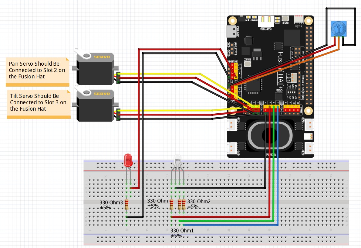
This is the schematic we are using for the project:
This is the code we developed in the video:
|
1 2 3 4 5 6 7 8 9 10 11 12 13 14 15 16 17 18 19 20 21 22 23 24 25 26 27 28 29 30 31 32 33 34 35 36 37 38 39 40 41 42 43 44 45 46 47 48 49 50 51 52 53 54 55 56 57 58 59 60 61 62 63 64 65 66 67 68 69 70 71 72 73 74 75 76 77 78 79 80 81 82 83 84 85 86 87 88 89 90 91 92 93 94 95 96 97 98 99 100 101 102 103 104 105 106 107 108 109 110 111 112 113 114 |
from fusion_hat.pwm import PWM from fusion_hat.stt import STT import threading from queue import Queue from time import sleep from fusion_hat.tts import Piper tts = Piper() tts.set_model('en_US-kristin-medium') msg = 'Speak your favorite color, and your wish is my command' tts.say(msg,stream=False) redPin = 5 greenPin = 6 bluePin = 7 redLED= PWM(redPin) greenLED=PWM(greenPin) blueLED=PWM(bluePin) rVal=0 gVal=0 bVal=0 stt = STT('en-us') running=True colorQ = Queue() def getColor(): print("Input Thread is Running") global running while running: print('What color: red, green, blue, cyan, magenta, yellow, off, quit') myColor = stt.listen(stream=False) myColor=myColor.strip() if myColor == 'quit': running = False msg = 'So Sorry to See you go, Please Call Me Again Soon' tts.say(msg, stream=False) break colorQ.put(myColor) print("Thread is Terminated") colorThread= threading.Thread(target=getColor,daemon=True) colorThread.start() print("Main Program is Started") try: while running: if colorQ.empty() == False: myColor = colorQ.get() print('Color: ',myColor) if myColor == 'off': rVal = 0 gVal = 0 bVal = 0 msg = 'Please bring back your beautiful colors!' tts.say(msg, stream=False) if myColor == 'red' or myColor=='read': rVal = 100 gVal = 0 bVal = 0 msg = 'I can not get you out of my head, so I will turn it red' tts.say(msg, stream=False) if myColor == 'green': rVal = 0 gVal = 100 bVal = 0 msg = 'Because I want you to be seen, I will turn it green' tts.say(msg, stream=False) if myColor == 'blue': rVal = 0 gVal = 0 bVal = 100 msg = 'Because I love you, I will turn it blue' tts.say(msg, stream=False) if myColor == 'cyan': rVal = 0 gVal = 100 bVal = 25 msg = 'You turn my world cyan and bright, what a beautiful sight!' tts.say(msg, stream=False) if myColor == 'magenta': rVal = 100 gVal = 0 bVal = 100 msg = 'You Light my Magenta Fire, You are my burning Desire' tts.say(msg, stream=False) if myColor == 'yellow': rVal = 100 gVal = 25 bVal = 0 msg = 'You are such a handsome fellow, I will turn it yellow' tts.say(msg, stream=False) myColor = 'null' redLED.pulse_width_percent(rVal) greenLED.pulse_width_percent(gVal) blueLED.pulse_width_percent(bVal) redLED.pulse_width_percent(0) greenLED.pulse_width_percent(0) blueLED.pulse_width_percent(0) redLED.enable(False) greenLED.enable(False) blueLED.enable(False) print("LEDs are Released") print("Program is Terminated") except KeyboardInterrupt: running = False redLED.pulse_width_percent(0) greenLED.pulse_width_percent(0) blueLED.pulse_width_percent(0) redLED.enable(False) greenLED.enable(False) blueLED.enable(False) print("LEDs are Released") print("Program is Terminated") |