Today we are going to start a new series of lessons that will allow you to take your Arduino projects up to the next level. Hopefully you have been through my 20 lessons on using the Arduino. If you are not familiar with the Arduino, you should start with those lessons. If you are familiar with Arduino, you can just right into this series of Lessons.
One of the major limitations of the Arduino IDE is its limited ability to interact with the user. You can print text to a simple serial monitor text box, or get text input from the user. You can open up a new world of possibilities by using the programming language python to interact with the Arduino. Python combined with Arduino is a powerful combination what will drastically increase the WOW factor of your projects.
The video above will show a cool project that will hopefully motivate you to undertake this series of lessons. Python is a really cool language, and now that you know Arduino, it will be a breeze to learn Python!
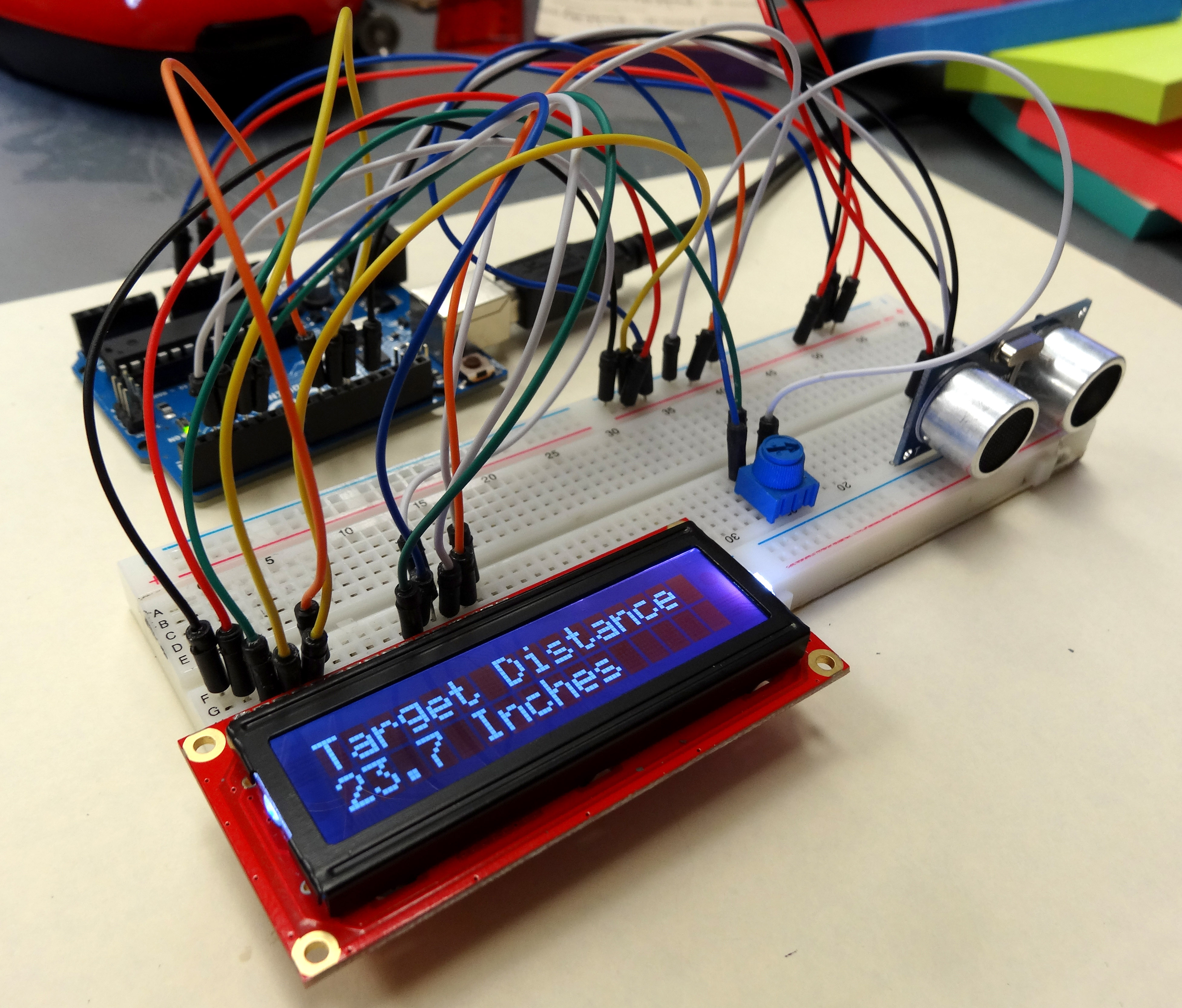
In LESSON 18 you learned how to use an ultrasonic sensor to measure distance, and in LESSON 19 you learned how to connect an LCD to the arduino. In this lesson we will combine what you have learned to create a circuit for measuring distance, and displaying results on an LCD display.
This circuit displays the distance you measure on a cool LCD.
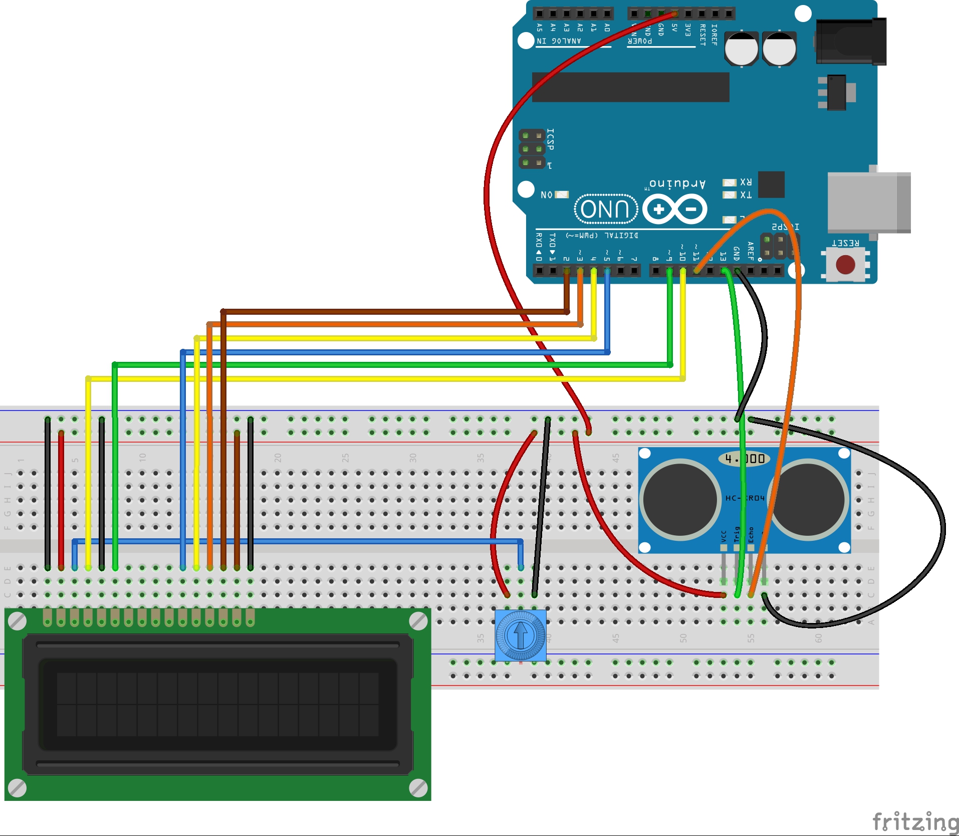
You can use the schematic below to connect the circuit. If you did LESSON 19, you should already have the LCD hooked up. For more info on connecting to the LCD, and how it works, review LESSON 19. This schematic is for the LCD in the Sparkfun Inventor Kit, or similar LCD. If you have a different LCD, you will have to determine the proper connections. There are some helps in LESSON 19. If you need the ultrasonic sensor, you can pick one up HERE.
This diagram shows how to connect my LCD to the Arduino.
Be very careful connecting the circuit. Check your work, and it helps to work with a Buddy. Have one person looking at the schematic, and one looking at the circuit. Sometimes it is easier to get it right working in pairs.
Now the objective of this project is to measure distance using the ultrasonic sensor, and then display that value on the LCD display. You should have the skills you need from the earlier lessons. Try and do this project on your own, but if you get stuck, you can look at my code below. As always, don’t copy and paste my code, but it should be used as a guide to help you write yours if you get stuck.
Your assignment is to get this project going, and show that you can measure distance and then display it on the LCD. After showing me your work, then you need to take the project in your own unique direction. What can you make based on what you have learned in the last few lessons. You should use some combination of Ultrasonic Sensor, LCD, and Servo to make a project or product or your own invention. You have the technical skills, you have the equipment, now go be creative!
In this lesson we are going to learn to use an LCD display. This really allows us to take our Arduino projects to that next level! We will first get the LCD hooked up and show we can display a simple welcome message. Then we will use it to display the distance measurement being made from the ultrasonic sensor. So, do not take your project apart from LESSON 18.
This circuit displays the distance you measure on a cool LCD.
This table shows you how to connect your Sparkfun Inventor Kit LCD to your arduino. (If you do not have the kit, and want an LCD like the one in this tutorial you can order it HERE.) When oriented like the photograph above, pin one is the pin in the upper left corner, and they are numbered sequentially from left to right. The table below shows the connections needed to allow the arduino to work with this LCD using the code we will write in this lesson. The pinout of other LCD might be different, but if you connect the LCD named pins in column 2 to the Arduino pins in column 3 in the table below, you should be able to get many of the 16X2 LCD’s to work.
Connections for Sparkfun Inventor Kit LCD
(for others column 1 might be different)
LCD Pin #
LCD PIN NAME
Arduino Pin
1
VSS
GND
2
VDD
5V
3
V0
Pot Center Pin
4
RS
10
5
RW
GND
6
E
9
7
DB0
NOT CONNECTED
8
DB1
NOT CONNECTED
9
DB2
NOT CONNECTED
10
DB3
NOT CONNECTED
11
DB4
Pin 5
12
DB5
Pin 4
13
DB6
Pin 3
14
DB7
Pin 2
15
Backlight LED +V
5V
16
Backlight LED GND
GND
For this project, you can use the table above to connect your LCD to the Arduino. The diagram below is a graphical representation of the connections for LCD like mine.
This diagram shows how to connect my LCD to the Arduino.
These LCD are tricky to hook up because there are so many wires. You have to be very careful, and you have to make sure your LCD is oriented properly. Check the spec sheet that comes with you LCD carefully to verify connections are correct.
Once the LCD is wired up, it is fairly straightforward to use.
At the top of your code, you will want to make sure that you load the LCD library. This is a standard library that comes with your arduino software. You load the library by putting the following code at the top of your program:
Arduino
1
#include <LiquidCrystal.h>
Also at the top of the code, you want to create you LCD object, which also tells Arduino how you are connected to it:
Arduino
1
LiquidCrystalLCD(10,9,5,4,3,2);//Create Liquid Crystal Object called LCD
The numbers tell Arduino that we have RS hooked to pin 10, E hooked to pin 9, DB4-DB7 connected to Arduino pins 5-2, as shown in the table above.
In the void setup, you will want to tell the Arduino that your LCD has 16 columns and 2 rows. You should put this code in your void setup, since you only need to do it one time:
Arduino
1
LCD.begin(16,2);
You are now just about ready to start sending messages to the LCD. You need to start by telling the Arduino where on the LCD to begin the message. Remember that it always wants column first, then row, and that it starts with ‘0’. Therefore, the upper left character would be column 0, row 0, or (0,0). To set the cursor to the upper left corner, you would send command:
Arduino
1
LCD.setCursor(0,0);//Set LCD cursor to upper left corner, column 0, row 0
So now lets make a simple Counter. We will count off seconds. We start by printing “My Timer” on the first row. We do that with the command:
Arduino
1
LCD.print("My Timer:");//Print Message on First Row
Now we would go to the second row and print a counter. Lets bring all the code together in the following working program.
LCD.setCursor(0,1);//Go to 1st column(column 0) and 2nd row(row 1)
LCD.print(myCounter);
LCD.print(" Seconds");
delay(1000);
}
}
Run this program. If you have your LCD hooked up correctly, you should see the counter working. If it is not showing, you probably have miswired the circuit. Go back and check your circuit carefully. You also might need to play with the setting on the potentiometer to get the contrast set correctly.
Now, watch the counter count up and down carefully. You should notice something peculiar as the counter counts backwards. What do you see that is not good? What you should see is that as you count down from 10 to 9, you end up with an extra ‘s’ on the word ‘Seconds’. You end up with ‘Secondss’. This is a vexing problem which occurs just about every time you try and use an LCD. The reason is that when you go from 10 to 9, printing the number goes from needing two digits to one digit. Then, when you print ‘Seconds’ it is shifted to the left by one character, and you are still left with the last ‘s’ from the previous time you printed ‘Seconds’. Hence you are left with a mess.
There are two ways to clear this up. One way would be to specifically set the cursor to a correct position before printing ‘Seconds’. This would put it in the same place every time, and alleviate the problem. The other possibility is to print a blank line each time through the loop to clear the second line of the LCD. This is something you need to play around with and understand, because it seems to come up every time I try and use an LCD. Look at this code, and try it, and make sure you understand why it fixes the problem.
LCD.setCursor(0,1);//Go to 1st column(column 0) and 2nd row(row 1)
LCD.print(" ");//Print blanks to clear the row
LCD.setCursor(0,1);//Go to 1st column(column 0) and 2nd row(row 1)
LCD.print(myCounter);
LCD.print(" Seconds");
delay(1000);
}
OK, your assignment is to play around with the LCD and become comfortable with it. Show me that you can make it do some new and interesting things. Write a program of your choosing that uses the LCD as a display. You might consider making it the display for one of the projects you did in one of our earlier lessons.
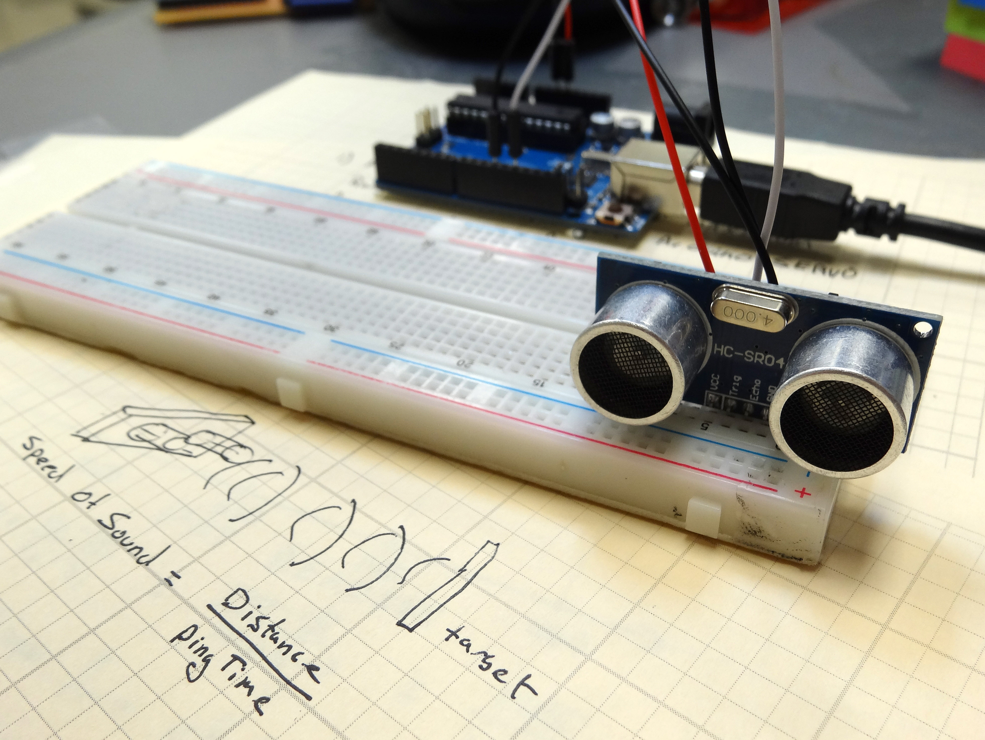
In Lesson 17 we learned to use an ultrasonic sensor to measure the speed of sound. There is a different way to use the sensor. Since we know the speed of sound, we can use it to measure distance, since d = r*t (distance = rate * time). You know the rate, that is the speed of sound. You can measure the ‘time’ using the ultrasonic sensor, just as you did in Lesson 17. This is the time for a ping to go from the sensor to the target and back. Knowing this, you can then calculate the distance to the target.
Arduino Distance Sensor Displays Measured Distance with a Servo
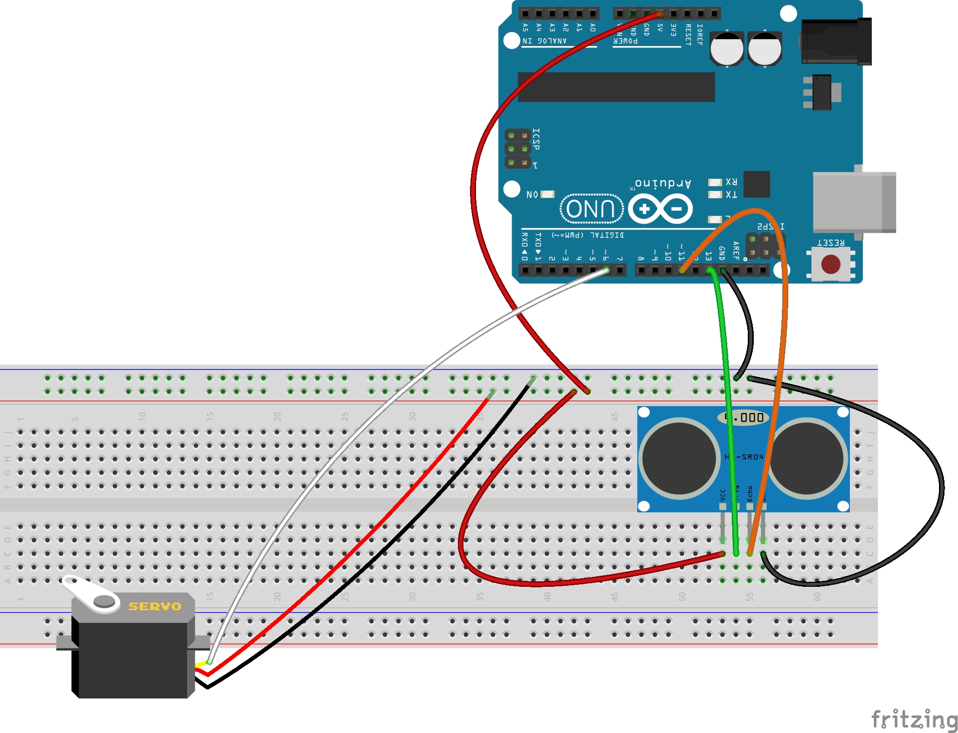
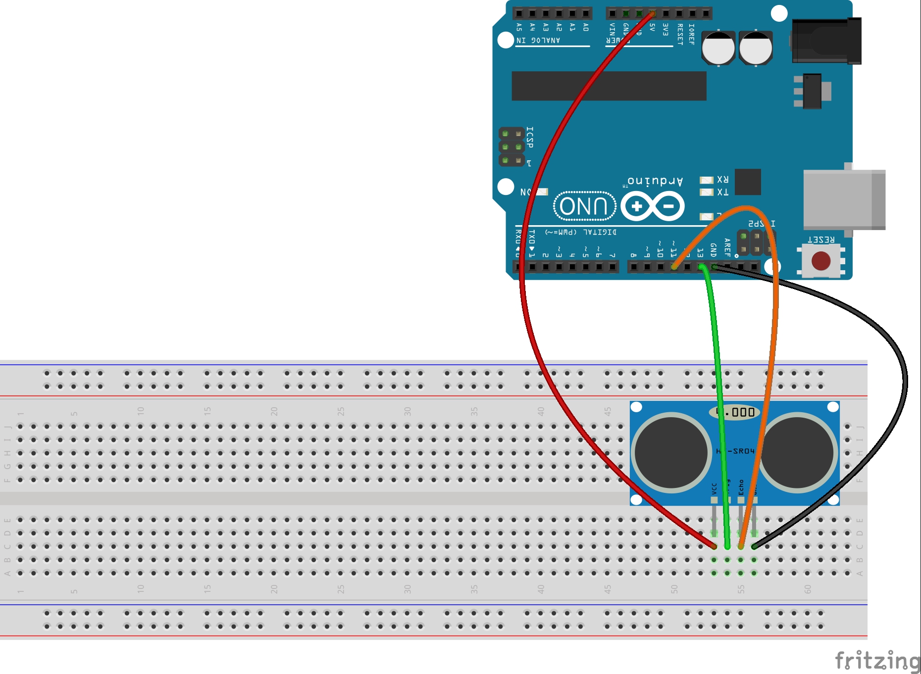
For you hackers, just jump right in and do the assignment. You should be able to do it with what you have already learned. What I want you to do, though, is come up with some creative way to display the distance . . . something better than just printing it on the Serial Monitor. I will make a scale and display it using a servo. You can do whatever you think would be most interesting. For those who need a little extra help, I will step you though my project below. The first thing you need is to hook up your circuit. I have the sensor hooked up like in Lesson 17 and have added a servo. The servo black wire needs to hook to ground, the red wire to 5V from the arduino, and the white wire, which is the control wire, I have hooked to pin 6 of the arduino. Remember that you need to verify that your servo will not draw too much current from the Arduino. The servos in the Sparkfun Inventor Kits work fine, and can be driven directly from the arduino 5V power pin. Also, your servo might have different colored wires. Many have Red for power, Orange for control , and Brown for Ground. Always confirm the color code with the data sheet for the specific servo you are using. Also, remember that before using a servo, you need to determine its suitable range of motion. This was explained in Lesson 16. For my project, I am using the following schematic. It would be better to hook to the ultrasonic sensor by putting the wires behind the sensor, so they do not interfere with the ‘ping’ coming from the front. I drew them in front so you could see them clearly, but wire them on the back side of the sensor.
Arduino Circuit for Measuring Distance.
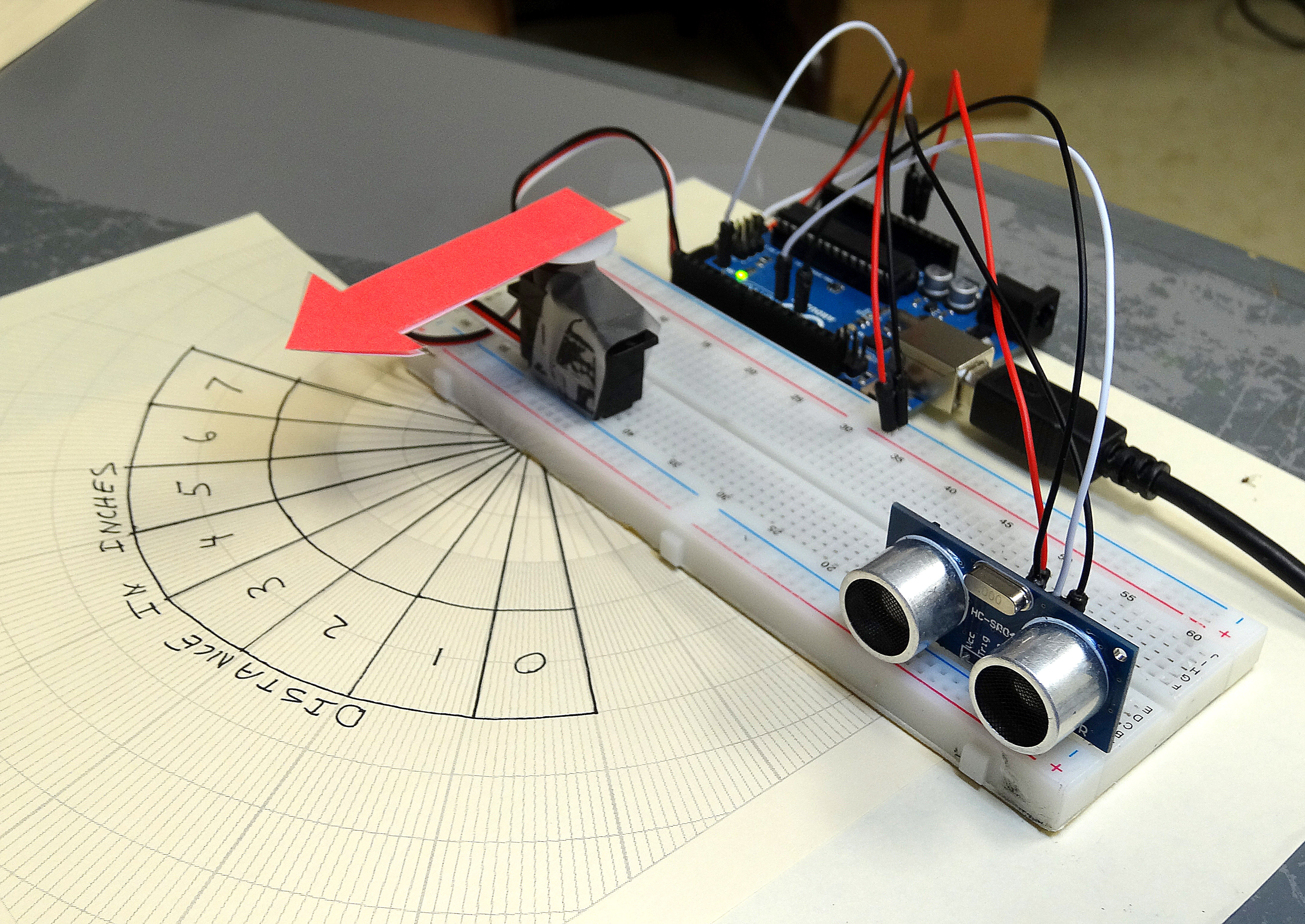
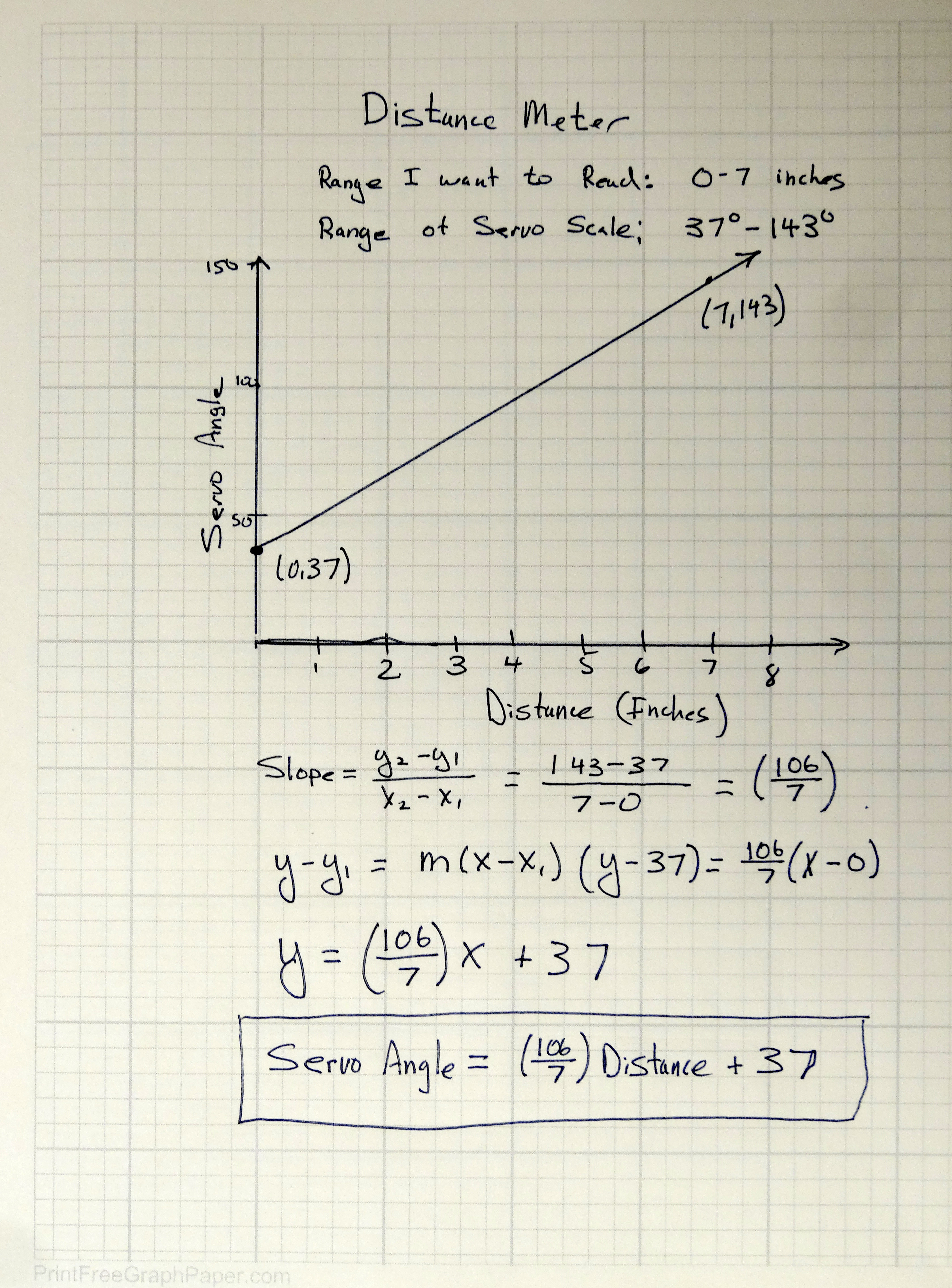
When you get your circuit set up, we will need to do some math. Our objective is to measure distances between 0 and 7 inches. This sensor could probably do a good job measuring distances up to three feet, but for this project we will focus on 0 to 7 inches. We then want to put a pointer on the servo, and have it point at a scale that will indicate distance. Since the servo swings in an arc, we can best thing about the output of the servo as an angle. On the scale I draw, I want to have the numbers be between angles of 37 degrees and 143 degrees. For a distance measured of 0 inches, I want the servo to point at 37 degrees. For a distance measured of 7 inches, I want to point to 143 degrees. Then, everything should scale between those numbers. You can see that I drew my scale for my servo above on a piece of polar graph paper. Polar graph paper makes it easy to draw specific angles and ranges of angle. You can print your own polar graph paper at HERE. Now, the math that has to be done is to calculate the angle you should set your servo at based on what distance measurement you are reading. The numbers have to match the scale you draw for the servo. For mine, I want a measurement of 0 inches to put the servo at 37 degrees, and a measurement of 7 inches to put the servo at 143 degrees. These match the positions of the ‘0’ and ‘7’ on my scale. By this time you should be comfortable doing the math, but if you need help, you can check my notes below.
These notes show you how to calculate servo position based on measured distance.
You will need to draw our own servo scale. You can arrange the scale however you like, but in the end, you have to do the math so that your servo points at the right distance number on your scale.
With that out of the way, we now need to do the coding. There is not really anything new to learn as far as coding goes. This is really a combination of what you learned in lesson 16 and lesson 17. In this project though, instead of measuring the speed of sound, we will be measuring the distance to a target, given the known speed of sound. Then we use the math above to calculate where to point the servo. The video above will take you through the code step by step, but I include the code below. You should not copy and paste the code, but just look at it if you get stuck. For those of you in my class when I check you project for a grade, I will be looking to see if you are working independently, or just copying what I am doing.
Arduino
1
2
3
4
5
6
7
8
9
10
11
12
13
14
15
16
17
18
19
20
21
22
23
24
25
26
27
28
29
30
31
32
33
34
35
36
37
38
39
40
41
42
43
44
45
46
47
48
#include <Servo.h> //Load Servo Library
inttrigPin=13;//Sensor Trip pin connected to Arduino pin 13
intechoPin=11;//Sensor Echo pin connected to Arduino pin 11
intservoControlPin=6;//Servo control line is connected to pin 6
floatpingTime;//time for ping to travel from sensor to target and return
floattargetDistance;//Distance to Target in inches
floatspeedOfSound=776.5;//Speed of sound in miles per hour when temp is 77 degrees.
floatservoAngle;//Variable for the value we want to set servo to.
ServomyPointer;//Create a servo object called myPointer
voidsetup(){
// put your setup code here, to run once:
Serial.begin(9600);
pinMode(servoControlPin,OUTPUT);
pinMode(trigPin,OUTPUT);
pinMode(echoPin,INPUT);
myPointer.attach(servoControlPin);//Tell arduino where the servo is attached.
}
voidloop(){
// put your main code here, to run repeatedly:
digitalWrite(trigPin,LOW);//Set trigger pin low
delayMicroseconds(2000);//Let signal settle
digitalWrite(trigPin,HIGH);//Set trigPin high
delayMicroseconds(15);//Delay in high state
digitalWrite(trigPin,LOW);//ping has now been sent
delayMicroseconds(10);//Delay in low state
pingTime=pulseIn(echoPin,HIGH);//pingTime is presented in microceconds
pingTime=pingTime/1000000;//convert pingTime to seconds by dividing by 1000000 (microseconds in a second)
pingTime=pingTime/3600;//convert pingtime to hourse by dividing by 3600 (seconds in an hour)
targetDistance=speedOfSound*pingTime;//This will be in miles, since speed of sound was miles per hour
targetDistance=targetDistance/2;//Remember ping travels to target and back from target, so you must divide by 2 for actual target distance.
targetDistance=targetDistance*63360;//Convert miles to inches by multipling by 63360 (inches per mile)
Serial.print("The Distance to Target is: ");
Serial.print(targetDistance);
Serial.println(" inches");
servoAngle=(106./7.)*targetDistance+37;//Calculate Servo Angle from targetDistance
myPointer.write(servoAngle);//write servoAngle to the servo
Serial.println(servoAngle);
delay(100);//delay tenth of a second to slow things down a little.
}
Now your assignment is to come up with a new and different way to display the distance. On this new assignment measure distances between 0 and 18 inches. Figure out a cool way to convey that distance to the user. Think of a good idea. If you are having trouble coming up with an idea, maybe build a bar graph with 10 LED’s, and the number of lit LED’s indicating distance. In any event, you will need to do your math on the project, and an important part of the grade is showing me your graph where you map your output values onto your input values, like I did above.
Now that we know the basics of Arduino from the first 15 lessons, we can begin to focus on more and more cool projects.
Simple Circuit for measuring the speed of sound
I think you will be surprised to see how many sophisticated things you can do with the simple arduino skills you have already learned. In this project, we are going to measure the speed of sound using the arduino and an ultrasonic sensor. We will use the Virtuabotix ultrasonic sensor which you can get HERE for about nine bucks. This sensor measures the time it takes an ultrasonic ping to go out, bounce off a target, and come back. The time it takes for the ping to leave and come back to the sensor depends on the speed of sound and the distance to the target. This sensor works in the same way a bat uses high pitched tones to navigate in the dark. It is also the same principle used in submarine sonar. The Arduino circuit for this project is very simple, and shown in the following schematic:
Simple Circuit for Measuring Speed of Sound
This sensor is fairly easy to use. To hook it up, we take the sensor VCC pin and hook it to the arduino 5V pin. We take the sensor GND and connect to Arduino GND. The Trig pin on the sensor we take to pin 13 on the arduino and the Echo pin on the sensor we connect to the arduino pin 11.
The sensor works as follows. You take the trigger pin LOW with a digital write. You then pause, take the trigger pin HIGH, pause, and then take the trigger pen LOW again. This LOW-HIGH-LOW sequence creates a high pitched ultrasonic tone, or ping, which is sent out from the sensor. This ping will go out and bounce off the first thing in front of it, and bounce back to the sensor. The sensor will output a HIGH pulse on its echo pin, and the length of the pulse in microseconds indicates the time it took the ping to travel to the target and return. We can measure the length of this pulse using the pulseIn command we learned in lesson 15.
Once you make the pulseIn measurement, and know the time it took for the ping to travel to the target and return, you can use that to calculate the speed of sound. Since
distance = rate * time.
Distance is the distance traveled by the ping, time is how long it took the ping to travel to the target and return. With this we can rearrange the equation to solve for rate, which would be the speed of sound:
rate = time/distance
Since pulse in returns the ping travel time in microseconds, and if you measure the distance to the target in inches, the units on the rate will be in inches per microsecond. We would need to use dimensional analysis to convert this to miles per hour as follows:
(rate in inches/mircrosecond)*(1000000 microsecond/second)*
(3600 seconds/hour)*(1 mile/63360 inches)
This will then give rate in miles per hour, as you can see as the units cancel out. The video explains this in more detail.
Key thing to remember in doing this calculation is that the ping has to travel to the target and then return. If the target is 6 inches from the sensor, how far did the ping travel? It traveled 12 inches. Six to get to the target and six to return from the target.
Try and put it all together into a program that will measure the speed of sound. I have included the code below. Try and write the program yourself, but if you get stuck you can look at the code below. It is important not to copy and paste this code, but only use it as a guide. You need to type your programs in yourself.
Arduino
1
2
3
4
5
6
7
8
9
10
11
12
13
14
15
16
17
18
19
20
21
22
23
24
25
26
27
28
29
30
31
inttrigPin=13;//Sensor Trip pin connected to Arduino pin 13
intechoPin=11;//Sensor Echo pin connected to Arduino pin 11
floatpingTime;
floatspeedOfSound;
inttargetDistance=6;//Distance to Target in inches
voidsetup(){
// put your setup code here, to run once:
Serial.begin(9600);
pinMode(trigPin,OUTPUT);
pinMode(echoPin,INPUT);
}
voidloop(){
// put your main code here, to run repeatedly:
digitalWrite(trigPin,LOW);//Set trigger pin low
delayMicroseconds(2000);//Let signal settle
digitalWrite(trigPin,HIGH);//Set trigPin high
delayMicroseconds(10);//Delay in high state
digitalWrite(trigPin,LOW);//ping has now been sent
pingTime=pulseIn(echoPin,HIGH);//pingTime is presented in microceconds
speedOfSound=(targetDistance*2)/pingTime*(1000000)*3600/63360;//converts to miles per hour
Serial.print("The Speed of Sound is: ");
Serial.print(speedOfSound);
Serial.println(" miles per hour");
delay(1000);
}
Check this out and see how close it is to published values for the speed of sound. Pretty Cool!
Making The World a Better Place One High Tech Project at a Time. Enjoy!
We use cookies to ensure that we give you the best experience on our website. If you continue to use this site we will assume that you are happy with it.Ok