In this video tutorial we show how the MPU6050 can be used to measure acceleration in the x, y, and z directions, that is, Ax, Ay, and Az. We also introduce the idea of plotting the data to the Arduino Serial Plotter to make visualization of the data easier.
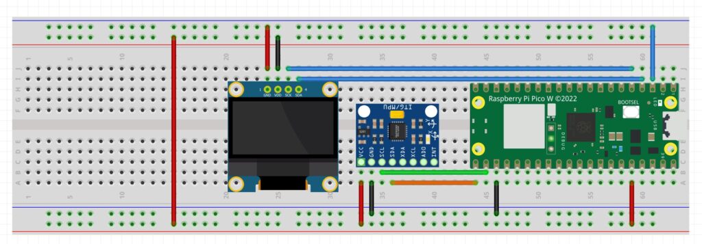
Below is the schematic we are using to access the MPU6050 on the GY-87 module.
Schematic for connecting the GY-87 module to the Arduino
Below is the code which we developed in the lesson to measure acceleration in all three axis.
In this video lesson we will show you how to incorporate accelerometers into your Arduino projects. Your Sunfounder kit includes the GY-87 IMU module. This module contains a BMP180 pressure sensor, which we have already used in earlier lessons, and an MPU6050 6 axis IMU. The MPU6050 includes 3 accelerometers and 3 gyros. In today’s lesson, we learn how to use the MPU6050 accelerometers. I will explain how these MEMS bases accelerometers work, and how we can use them in our project.
This is the schematic we use in todays lesson.
Schematic for connecting the GY-87 module to the Arduino
For your convenience, the code developed in the lesson is presented below:
In this video lesson I show you how to remove long term steady state error from the tilt values calculated from the MPU6050 IMU. We are using the following schematic for our prototype.
Schematic for Creating a Tilt Meter
For your convenience, this is the code we developed in the video.
In this video lesson we show how to create a complimentary filter such we get pitch and roll data from the MPU6050 which is quick and responsive, accurate, and low noise. We are using the following schematic:
In this video lesson we describe how to measure roll, pitch, and yaw using the MPU6050. We describe the issues associated with drift in these gyros and will propose a path forward in dealing with the drift issue.
We are using the following circuit for this project:
Schematic for Creating a Tilt Meter
And this is the code we develop in today’s lesson.
1
2
3
4
5
6
7
8
9
10
11
12
13
14
15
16
17
18
19
20
21
22
23
24
25
26
27
28
from imu import MPU6050
from machine import I2C,Pin
import math
import time
i2c=I2C(0,sda=Pin(16),scl=Pin(17),freq=400000)
mpu=MPU6050(i2c)
roll=0
pitch=0
yaw=0
tLoop=0
cnt=0
whileTrue:
tStart=time.ticks_ms()
xGyro=mpu.gyro.x
yGyro=mpu.gyro.y
zGyro=mpu.gyro.z
roll=roll+yGyro*tLoop
pitch=pitch+xGyro*tLoop
yaw=yaw+zGyro*tLoop
cnt=cnt+1
ifcnt==10:
cnt=0
print('R: ',roll,'P: ',pitch,'Y: ',yaw)
tStop=time.ticks_ms()
tLoop=(tStop-tStart)*.001
Making The World a Better Place One High Tech Project at a Time. Enjoy!
We use cookies to ensure that we give you the best experience on our website. If you continue to use this site we will assume that you are happy with it.Ok