Category Archives: Tutorial

Beaglebone Black LESSON 12: Control a Servo from Python Using PWM

This lesson will show how to use Python running on the Beaglebone Black to control the position of a servo. First, I am using a small servo that I have verified can be powered from the Beaglebone Black without drawing too much current. All servos are different, so if you are unsure of the current requirements of your servo, it is safest to power it from an external 5 Volt power source. You can still control it through the control line connected to the Beaglebone Black, just make sure the servo and Beaglebone have a common ground.

Beaglebone Black Servo
Control of Servo From Beaglebone Black.

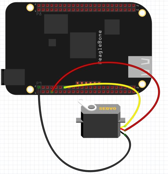
Most all servos have three wires; Power, Control, and Ground. For my servo, Control is Yellow, Power is Red, and Ground is Black. If you have a different servo, check the data sheet to see what colors are Control, Power and Ground on your servo. Note we are using pin P9_2 as ground, P9_7 as 5V power, and P9_14 as our control pin.

We will be controlling the position of the servo using PWM. We will have to play around with our individual servo to determine precisely what signal pulse width will result in the servo being in the full left position, and what pulse width will result in the servo being in the full right position.

For most servos, full left is somewhere around 1 milliseconds, and the pulse width that will give us full right position is about 2 milliseconds. These are ballpark numbers, and we will have to play around with things to find the exact values for our servo.

We will set up a 50 Hz PWM signal. A 50 Hz signal has a period of:

period = 1/frequency = .02 seconds = 20 miliseconds.

Hence, if we want to get to about the full left position we would want a duty cycle of about 5%. Because 20 milliseconds x .05 = 1 milliseconds. This one millisecond pulse width should put the servo about in the full left position. Similarly for the full right position, we would want a duty cycle of 10%, because that would give us a pulse width of 2 milliseconds, since:

PulseWidth = Period x DutyCycle

PulseWidth = 20 x .1 = 2 milliseconds.

We can use the following code to determine precisely for our servo what dutyCycle will give the precise full left and full right positions.

For my servo, running a 50 Hz PWM singnal, I find that a duty cycle of 2% puts it in the full left position and a duty cycle of 12% puts it in the full right position.

Now we would like to be able to just specify an angle we want and have it go to that angle. If we want an angle of 0 degrees we would apply a 2% duty cycle. This value is for my servo. You will have to play around with your servo and the code above to find what this number is for you. But for me, I have the point:

(0,2)

That is to say when I desire an angle of 0 on the servo, I should apply a dutyCycle of 2 to the PWM pin. Similarly, when I desire 180 degrees, I should apply a dutyCycle of 12. (Again, this number might vary for your servo). For my servo, I get the point:

(180, 12)

We can fit a line to these points, which would then allow us to calculate the dutyCycle for any desired angle. The slope from the two points above would be:

m=(y2-y1)/(x2-x1)=(12-2)/(180-0) = 10/180= 1/18

Using the point slope form of the line, we would get

y-y1 = m (x- x1)

y – 2 = 1/18( x – 0)

y= 1/18*x + 2

Now putting in our actual variable names we get:

dutyCycle = 1/18*desiredAngle + 2

You can develop the same type equation just using the values suitable for your servo from the experiment above.

Now we can use this code to smoothly move the servo to any desired position.


Beaglebone Black LESSON 9: Reading Analog Inputs from Python

If you went through our series of lesson on the Raspberry Pi, you will remember that we found the major limitation of the Pi is that it has no analog input pins. Luckily, the Beaglebone Black as a number of analog input pins, so we can greatly expand the scope of projects we can do.  The pinout below shows the pins that are available on the Beaglebone Black for analog input. (If you do not already have your Beaglebone Black, you can pick one up HERE.)

Beaglebone Black Pinout
Default Pin Configuration for the Beaglebone Black Rev. C.

You can see the blue shaded pins in the diagram above are for analog input.

A couple of very important points. These pins are designed to read analog voltages between 0 and 1.8 volts. Applying voltages above 1.8 volts can burn out the pin, or even smoke the Beaglebone. Hence, as you set up voltage divider circuits you must ensure they have a rail of 1.8 Volts, to ensure that the analog in pins will never see more than 1.8 Volts. Luckily, the Beaglebone provides a handy 1.8 Volt reference signal on pin 32  (on P9 header). Always use pin 32 as your reference rail when working with analog inputs. Similarly, you should use pin 34 (on P9 header) as your reference ground on your analog input circuits.

To demonstrate how to do analog reads, we will set up a simple voltage divider using a potentiometer. Go ahead and hook up your circuit as follows:

Potentiometer
A Simple Voltage Divider Using a Potentiometer

Note we are using P9_32 as the reference voltage on the voltage divider, we are using P9_34 as the reference ground, and we are using P9_33 as the analog sense pin.

With this circuit hooked up we are ready to develop some code. In the attached video we take you through this program step-by-step to show you how you can make analog readings from the potentiometer using python.

 Note the analog read returns a number between 0 and 1, which is proportional to the applied voltage. Hence to convert to actual voltage, we multiply this read value by 1.8 Volts.

Beaglebone Black LESSON 6: Control PWM Signals on Output Pins from Python

In Lesson 4 and Lesson 5 we showed how to do digital writes to the GPIO pins using Python. (If you have not picked up your Beaglebone Black Rev. C yet, you can get one HERE) With digital writes, we could generate an output of 3.3 volts or 0 volts. For many applications, we would like analog output, or the in between voltages. The Beaglebone Black, as with most microcontrollers, can not produce true analog output. However, for many applications, an analog output can be simulated by creating a fast on/off sequence where the analog value is simmulated by controlling the ratio of on time and off time. This technique is called Pulse Width Modulation, or more simply, PWM. Consider a 3.3 volt signal, which is turning on and off with a frequency of 50 Hz.  A 50 Hz signal has a Period of: Period=1/frequency=1/50=.02 seconds, or 20 milliseconds. If during that 20 millisecond period, the signal was “High” for 10 milliseconds, and “Low” for 10 milliseconds, the signal would act like a 1.65 volt analog signal. The output voltage therefor could be considered the rail voltage (3.3 volts) multiplied by the duty cycle (percentage of time the signal is high.

For the Beaglebone Black, only certain pins can be used for PWM signals.

Beaglebone Black Pinout
Default Pin Configuration for the Beaglebone Black Rev. C.

In the chart above, the purple pins are suitable for PWM output. You can see there are 7 pins which can produce PWM signals. In this lesson we show you how to control those pins.

In order to control PWM signals, we are going to use Python and the Adafruid_BBIO Library. Recent versions of Beaglebone Black Rev. C are shipped with the library already part of the operating system. If you are getting errors indicating that you do not have the library, update your operating system to the latest Debian image for the Beaglebone Black.

In order to use PWM in Python, you must load the Adafruit Library. If you have the recent versions of Debian Wheezy for the Beaglebone black, the library will already be on your system. If you do not do an update and upgrade on your operating system.

To begin with, you will need to load the library.

 Next up, you will need to start the PWM on the pin you are using. We will use pin “P8_13”. Remember you must use one of the purple colored pins on the chart above. We start the PWM with the following command:

This command puts a 1000 Hz signal (Period of 1 mSec) on pin P8_13, with a duty cycle of 25%. This should yield a simulated analog voltage of .84 volts.

We can change the duty cycle after this initial setup with the command:

This command would change the duty cycle to 90%, which would simulate a voltage of 3.3 * .9 =  2.97 volts.

You can also change the frequency of the signal using the command:

This would change the frequency to 100 Hz (Period of 10 mSec). Changing the frequency does not really affect the net result of PWM in most applications, although it does matter for many servo applications.

After you are done, you can stop the PWM with the command:

And always remember to clean up after yourself with:

Play around with the Python Program below. Connect a DVM to your Beaglebone Black, and measure the DC voltage at the output pin. The DVM should show your anticipated voltages.

Considering that the simulated analog voltage V=3.365 X Duty Cycle, how would modify the program above to ask the user for the Voltage he desires, and then calculate the duty cycle that would give that voltage. Your assignment is to modify the program above where the user inputs desired voltage, and DC is calculated. Use a DVM to check your results

Comparing the Arduino, Raspberry Pi Model 2, and Beaglebone Black

In this video we do a head to head comparison of the Arduino, Raspberry Pi Model 2, and the Beaglebone black. We compare the pros and cons of each platform and discuss how to decide which platform to learn on and which is best for different types of projects.

You can pick up the gear discussed in this video below:

Arduino: This is a great place to start, and the device is very affordable.

Sparkfun Inventor Kit: Everything you need to learn microcontroller programming and circuits. This is the kit we use in our Arduino Lessons, and even includes the Arduino.

Raspberry Pi Kit: This kit has everything you need to follow along on our Raspberry Pi Lessons.

Raspberry Pi: If you already have the cords and cables, you can buy just the Raspberry Pi.

Beaglebone Black: We are not working on a series of lessons showing you how to use the Beaglebone Black. Now would be a good time to go ahead and order your Beagle.

I hope you enjoyed this video lesson, and hope you will jump in and take our lessons on using the Arduino, Raspberry Pi, and the Beaglebone Black

Raspberry Pi LESSON 29: Configuring GPIO Pins as Inputs

We are now ready to learn how to “read” values from the Raspberry Pi GPIO pins. In order to demonstrate this, we will show a simple example using buttons. If you ordered the Raspberry Pi kit we recommend, you already have everything you need, or you can pick your kit up HERE. To start with, you need to put together a simple circuit that connects two push buttons to your Raspberry Pi. Connect according to this schematic.

Raspberry Pi Buttons
Simple Circuit Connecting Two Push Buttons to the Raspberry Pi

Note that one leg of each button is connected to the ground rail on the breadboard, that is connected to the Pi ground at physical pin 6. Then we connect the left leg of the left button to physical pin 16, and the left leg of the right button to physical pin 12.

In order to read the state of these buttons, that is, whether they are being pressed or not, we need to write a python program. To begin with we must import GPIO library and specify that we want to

 Now we are ready to set the pin modes on the pins we are using. We are using pins 12 and 16. We will set up variables so that we can reference the pins by descriptive variables.

Note in our GPIO.setup commands, we are not just defining the pins as inputs, we are also activating pullup resistors with

With this command, the raspberry pi places a pullup resistor between the designated pin and the 3.3 V rail. This means that if we simply read the pin, we will read a “1”, “True”, or “High”, since the pin will see the rail through the pullup resistor. If we connect the pin to ground by pressing a button or switch, the pin will then read a “0”, “False” or “Low” because it will be a straight connection to ground, and as current flows through the pullup resistor, the 3.3 Volts will drop across the pullup resistor. Hence, the pin sees 0 volts.

The result is that with the pullup resistor activated, the pin will always report a “1” until something connects the pin to ground, and then it will read a “0”. This configuration should work for most things, but if you are getting unpredictable results which can result from electrical noise, then try using external pullup resistors.

 Now we are ready to read the values from the pins.

Notice that we read from the pin using the GPIO.input command. Also note that for reliable results you need to usually put a small delay in your code. This will help debounce the button, and will also give more stable results.

OK, so our final code is as follows:

This code will sit and monitor the buttons, and when one is pressed it will report that that button has been pressed.