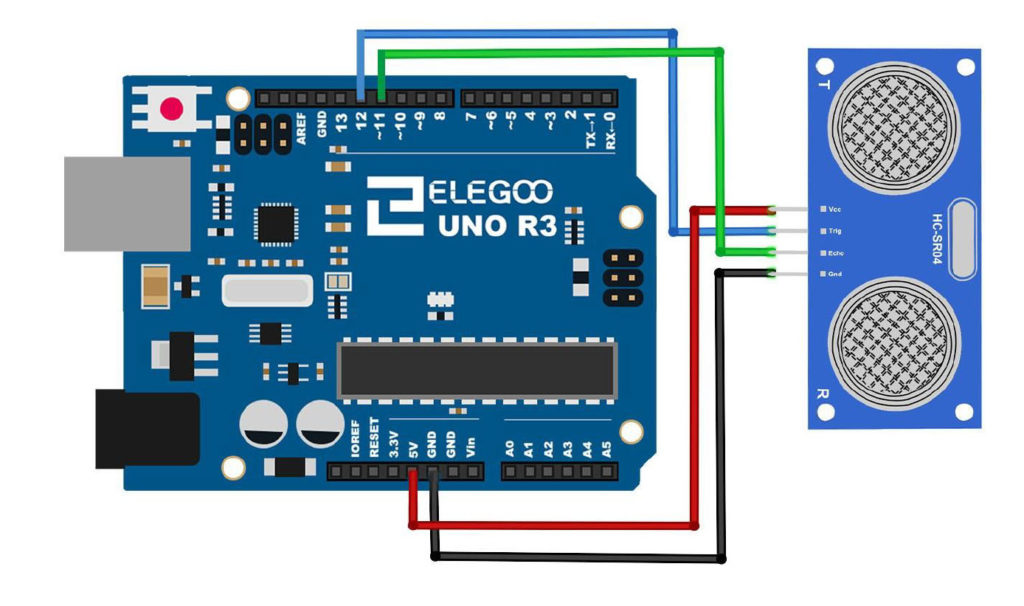
In this lesson we show how to program the speed of the Elegoo Smart Car Version 3.0 using the Infrared (IR) remote control. We take you through the process of using the remote step-by-step, and for your convenience we include the code below. If you want to play along at home, you can pick up your gear HERE.
|
1 2 3 4 5 6 7 8 9 10 11 12 13 14 15 16 17 18 19 20 21 22 23 24 25 26 27 28 29 30 31 32 33 34 35 36 37 38 39 40 41 42 43 44 45 46 47 48 49 50 51 52 53 54 55 56 57 58 59 60 61 62 63 64 65 66 67 68 69 70 71 72 73 74 75 76 77 78 79 80 81 82 83 84 85 86 87 88 89 90 91 92 93 94 95 96 97 98 99 100 101 102 103 104 105 106 107 108 109 110 111 112 113 114 115 116 117 118 119 120 121 122 123 124 125 126 127 |
int ENA=5; int ENB=6; int IN1=7; int IN2=8; int IN3=9; int IN4=11; float d; int degRot; int left; int right; int wv; float v; void setup() { // put your setup code here, to run once: Serial.begin(9600); pinMode(ENA,OUTPUT); pinMode(ENB,OUTPUT); pinMode(IN1,OUTPUT); pinMode(IN2,OUTPUT); pinMode(IN3,OUTPUT); pinMode(IN4,OUTPUT); digitalWrite(ENA,HIGH); digitalWrite(ENB,HIGH); } void loop() { v=1.5; wv=(v-.35)/.0075; left=wv; right=wv; setSpeed(left,right); forward(8,v); v=1.5; wv=(v-.35)/.0075; left=wv; right=wv; setSpeed(left,right); backward(8,v); while(1==1){ } } void setSpeed(int leftVal,int rightVal){ analogWrite(ENA,leftVal); analogWrite(ENB,rightVal); } void forward(float d, float v){ float t; digitalWrite(IN1,HIGH); digitalWrite(IN2,LOW); digitalWrite(IN3,LOW); digitalWrite(IN4,HIGH); t=d/v*1000; delay(t); stopCar(); } void backward(float d, float v){ float t; digitalWrite(IN1,LOW); digitalWrite(IN2,HIGH); digitalWrite(IN3,HIGH); digitalWrite(IN4,LOW); t=d/v*1000; delay(t); stopCar(); } void turnRight(int deg){ float t; digitalWrite(IN1,HIGH); digitalWrite(IN2,LOW); digitalWrite(IN3,HIGH); digitalWrite(IN4,LOW); t=deg/345.*1000.; Serial.println(deg); delay(t); stopCar(); } void turnLeft(float deg){ float t; digitalWrite(IN1,LOW); digitalWrite(IN2,HIGH); digitalWrite(IN3,LOW); digitalWrite(IN4,HIGH); t=deg/345.*1000.; Serial.println(deg); delay(t); stopCar(); } void stopCar(){ digitalWrite(IN1,LOW); digitalWrite(IN2,LOW); digitalWrite(IN3,LOW); digitalWrite(IN4,LOW); } void calF(){ digitalWrite(IN1,HIGH); digitalWrite(IN2,LOW); digitalWrite(IN3,LOW); digitalWrite(IN4,HIGH); delay(5000); stopCar(); } void calB(){ digitalWrite(IN1,LOW); digitalWrite(IN2,HIGH); digitalWrite(IN3,HIGH); digitalWrite(IN4,LOW); delay(5000); stopCar(); } void calR(){ digitalWrite(IN1,HIGH); digitalWrite(IN2,LOW); digitalWrite(IN3,HIGH); digitalWrite(IN4,LOW); delay(5000); stopCar(); } void calL(){ digitalWrite(IN1,LOW); digitalWrite(IN2,HIGH); digitalWrite(IN3,LOW); digitalWrite(IN4,HIGH); delay(5000); stopCar(); } |