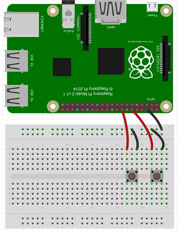
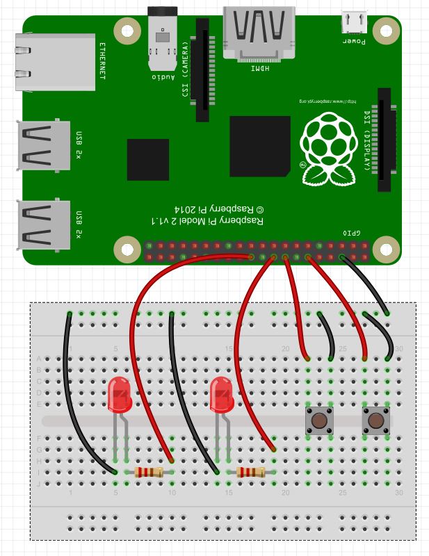
In this lesson we will show how you can control LED’s from push buttons. In order to get started, you will want to expand the circuit we built in LESSON 29 to include two LEDs. The schematic below shows how you will want to hook things up (Also, remember you can see the Raspberry Pi pinout in LESSON 25). Also, as we have mentioned before, if you want to follow along with us in these lessons you can get a kit that has all the gear you need HERE.
In the video lesson, we take you through the code step-by-step. We use the techniques learned in LESSON 29 to detect if a button has been pushed. We introduce two new variables, BS1 and BS2, so indicate the state of the LED’s. A BS1=False means the LED1 is off. A BS1=True means the LED is on. This concept allows us to determine whether we should turn the LED on or off when the button is pushed. Basically, we want to put it in the opposite state when a button is pushed. The code is below. The video shows how it works.
|
1 2 3 4 5 6 7 8 9 10 11 12 13 14 15 16 17 18 19 20 21 22 23 24 25 26 27 28 29 30 31 32 33 34 |
from time import sleep # Import sleep Library import RPi.GPIO as GPIO # Import GPIO Library GPIO.setmode(GPIO.BOARD) # Use Physical Pin Numbering Scheme button1=16 # Button 1 is connected to physical pin 16 button2=12 # Button 2 is connected to physical pin 12 LED1=22 # LED 1 is connected to physical pin 22 LED2=18 # LED 2 is connected to physical pin 18 GPIO.setup(button1,GPIO.IN,pull_up_down=GPIO.PUD_UP) # Make button1 an input, Activate Pull UP Resistor GPIO.setup(button2,GPIO.IN,pull_up_down=GPIO.PUD_UP) # Make button 2 an input, Activate Pull Up Resistor GPIO.setup(LED1,GPIO.OUT,) # Make LED 1 an Output GPIO.setup(LED2,GPIO.OUT) # Make LED 2 an Output BS1=False # Set Flag BS1 to indicate LED is initially off BS2=False # Set Flag BS2 to indicate LED is initially off while(1): # Create an infinite Loop if GPIO.input(button1)==0: # Look for button 1 press print "Button 1 Was Pressed:" if BS1==False: # If the LED is off GPIO.output(LED1,True)# turn it on BS1=True # Set Flag to show LED1 is now On sleep(.5) # Delay else: # If the LED is on GPIO.output(LED1,False) # Turn LED off BS1=False # Set Flag to show LED1 is now Off sleep(.5) if GPIO.input(button2)==0: #Repeat above for LED 2 and button 2 print "Button 2 Was Pressed:" if BS2==False: GPIO.output(LED2,True) BS2=True sleep(.5) else: GPIO.output(LED2,False) BS2=False sleep(.5) |