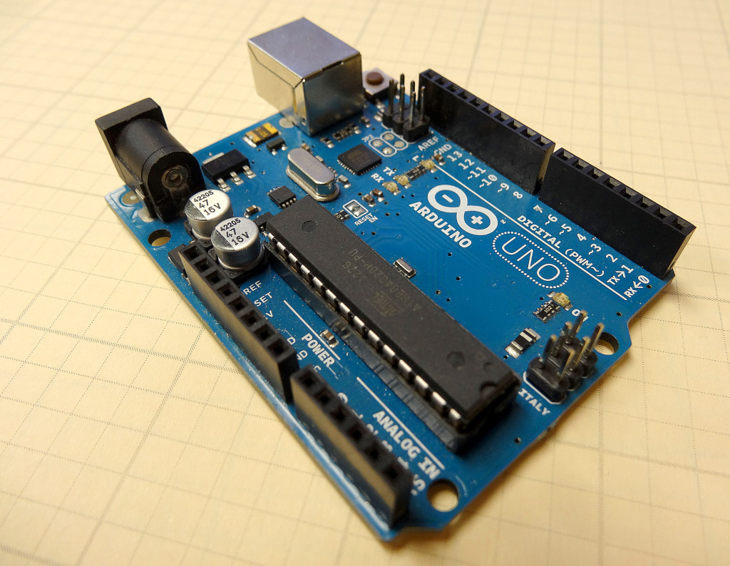
Guys, our original series on the Arduino Microcontroller was insanely popular. Those original lessons had some great technical content, but the production quality of the videos was pretty low. Because of that, I want to go in and redo the arduino tutorials, taking advantage of improved production capabilities I now have, and using fresh hardware and software. For those who have taken the original series, the first few lessons will be material you already have learned. You can choose to review the material, or just skip to the later lessons. An official Arduino Uno R3 is available HERE. In this new series of lessons, I will be using the sensor and other components found in this KIT.
So, enough of this small talk, lets get right into the new and improved lessons.
With the hardware linked to above, you will simply have to install the Arduino software. You can download the Arduino Software here. The installation is explained step-by-step in the above video, but it is pretty self explanatory.
The video takes you through the steps to make the on-board LED turn on, off, or blink. This will be your first few example programs, and hopefully you will see that programming is not that difficult. When you are done with this lesson, you will have written your first few programs. Enjoy!
In lesson 32 we introduced you to the concept of Arduino Functions. Functions are little blocks of code that allow you to break a complicated task down into small logical chunks of code. All the parts of the program shared the same set of variables. This is the easiest way to do functions, but is really not a good way of doing it. As programs get more complicated, with more functions, unexpected problems can arise if all the parts of the program are sharing the same variables. One function might inadvertently change a variable in use by another function causing unexpected problems. The best way to write modular code is to use local variables.
In Arduino, if a variable is declared at the top of the program, before the void setup, all parts of the program can use that variable. Hence, it is called a Global variable. On the other hand, if the variable is declared between a set of curly brackets, the variable is only recognized within that scope . . . that is, it will only be recognized and can only be used between that set of curly brackets.
For example, if a variable is declared in the void setup, it will not be recognized and can not be used in the void loop, because the void loop is within its own set of curly brackets.
Similarly, if there are two for loops inside the void loop, each for loop has its own set of curly brackets. If a variable is declared inside the first for loop, it will not be recognized inside the other for loop, and will not be recognized in the other parts of the void loop.
This might sound like a hassle, but using local variables really helps you stay out of trouble. The best way to do functions is to use local variable, and inside each function, the variables are declared that are needed by that function. Watch the video and I will give you clear examples of using local and global variables.
So far we have written programs as a long string of code, pretty much all in the void loop. As we begin to need to develop more complicated code, putting all the programming in the void loop can become unmanageable. It is easy to lose track of what we are doing. For more complicated programs, we want to break the problem up into manageable chunks of code. This is called modular program. We develop small modules that do specific tasks, and then our void loop simply calls these modules. The modules are called “Functions” in arduino.
Lets consider an example. Lets say we want to write an arduino program that prompts the user for the number of grades he has. Then it averages the grades, prints the grades and then prints the average. The following program would do this job, with all the code in the void loop:
Arduino
1
2
3
4
5
6
7
8
9
10
11
12
13
14
15
16
17
18
19
20
21
22
23
24
25
26
27
28
29
30
31
32
33
34
35
36
intnumGrades;
intj;
floatgrades[15];
floatbucket;
floatav;
voidsetup(){
// put your setup code here, to run once:
Serial.begin(9600);
}
voidloop(){
Serial.println("How Many Grades? ");
while(Serial.available()==0){
}
numGrades=Serial.parseInt();
for(j=1;j<=numGrades;j=j+1){
Serial.println("Please Input a Grade");
while(Serial.available()==0){
}
grades[j]=Serial.parseFloat();
}
for(j=1;j<=numGrades;j=j+1){
bucket=bucket+grades[j];
}
av=bucket/numGrades;
bucket=0;
Serial.println("Your Grades are: ");
for(j=1;j<=numGrades;j=j+1){
Serial.println(grades[j]);
}
Serial.println("");
Serial.print("Your Average is: ");
Serial.println(av);
Serial.println("");
}
You can see that the void loop is getting pretty complicated, and it would be easy to begin to lose track of what is going on. If we think about what we are trying to do, lets try to break it down more logically. These are the logical tasks we need to do:
Input Grades
Average Grades
Print Grades and Average
I think that is the logical way to break the program down. Hence, we need three modules or functions, which we could define as follows:
inputGrades();
avGrades();
printGrades();
We could call these three functions in the void loop. then down below the void loop we would need to define, or teach arduino what each of these functions do. In effect, the code in the example above is put down in three logical blocks, which we call functions. Notice that when we do that, the functions must be defined AFTER the void loop. That means it is done after the closing curly bracket for the void loop. Using functions, we can rewrite the program above as follows:
Arduino
1
2
3
4
5
6
7
8
9
10
11
12
13
14
15
16
17
18
19
20
21
22
23
24
25
26
27
28
29
30
31
32
33
34
35
36
37
38
39
40
41
42
43
44
45
46
47
48
49
50
intnumGrades;
intj;
floatgrades[15];
floatbucket;
floatav;
voidsetup(){
// put your setup code here, to run once:
Serial.begin(9600);
}
voidloop(){
inputGrades();
avGrades();
printGrades();
}
voidinputGrades(){
Serial.println("How Many Grades? ");
while(Serial.available()==0){
}
numGrades=Serial.parseInt();
for(j=1;j<=numGrades;j=j+1){
Serial.println("Please Input a Grade");
while(Serial.available()==0){
}
grades[j]=Serial.parseFloat();
}
}
voidavGrades(){
for(j=1;j<=numGrades;j=j+1){
bucket=bucket+grades[j];
}
av=bucket/numGrades;
bucket=0;
}
voidprintGrades(){
Serial.println("Your Grades are: ");
for(j=1;j<=numGrades;j=j+1){
Serial.println(grades[j]);
}
Serial.println("");
Serial.print("Your Average is: ");
Serial.println(av);
Serial.println("");
}
Notice now that the void loop is very simple to understand, since each function is logically named. Also, if we look down at the function definition, it is clear what each chunk of code does. In this example, we are using global variables, so each function, and the void loop are all working with the same set of variables. In future lessons we will look at the use of local variables, and then how that would affect the structure of our functions.
So fare we have used variable declarations like float, int, char and string. We have a variable declaration for any type of data we want to work with, but each of these allows storing a single piece of information. Often times we want to store more than just one variable, we want to store lists. We can store lists of variables in an array. We can make arrays of all the variable types we already know how to use. For example, if we wanted to store a single grade, we could use the following variable declaration:
float grade;
But, if we wanted to store a list of grades, we could define grades to be an array with the following command:
float grades[15];
This command creates an array called grades, which has 15 slots, so up to 15 grades can be stored. To specify which slot you are working with in your program, you simply reference the slot you are working with inside the brackets. For example:
grades[3]=97;
would set slot 3 in the grades array to the value 97.
Realize when you create an array in arduino, the first slot is slot zero, hence if you wanted to put a grade in the first slot you would use the command:
grades[0]=96;
You can create arrays for all the arduino variable types you are familiar with. You can create int, float, char and string arrays. The video above gives simple to understand examples of how to use arduino arrays.
In Lesson 28 and Lesson 29 we showed how to use simple software interrupts to do quick and easy tasks like turning an LED on or off. We emphasized the importance of just doing simple tasks, and to get in and out of the interrupt function as quickly as possible. It is sometimes necessary to do more sophisticated functions. For example, the Adafruit Ultimate GPS immediately begins sending serial data on powerup. Making matters worse, it sends big bursts of data, and then waits, and then later sends bursts of data again. The data that is sent needs to not just be read, but you must parse the data to make sense of it. Hence, you end up needing to do sophisticated functions to parse the data, but at the same time you have to make sure you do not miss any of the new incoming data. This requires a more thoughtful and sophisticated interrupt strategy.
First off, we will need a better software interrupt library. You should erase the TimerOne library you installed in Lesson 28, and replace it with the one here:
We use cookies to ensure that we give you the best experience on our website. If you continue to use this site we will assume that you are happy with it.Ok