
In today’s lesson in the AI on the Edge series, we’re adding a very important piece to our growing collection of skills — learning how to use the SSD1306 OLED display with the SunFounder Fusion AI Lab kit.
One of the key goals of this class is to build intelligent systems that can run completely on the edge — without needing to rely on the cloud. A big part of that is giving our edge devices the ability to communicate clearly with us. That’s exactly where the little SSD1306 OLED really shines. Whether you’re building a smart robot, an autonomous sensor node, or an AI-powered monitoring system, having a crisp, low-power display to show status, results, or even fun animations makes your project feel complete and professional.
In this video, we start with the basics and gradually build up. You’ll learn how to connect the OLED using I2C, initialize it with CircuitPython, and then use the PIL library to create images in memory before sending them to the screen. We explore loading different font sizes so you can create nice, readable layouts. Then we move into drawing shapes — rectangles, circles, and borders — before finishing with a fun bouncing ball animation that brings the whole thing to life.
This lesson is particularly important in our AI on the Edge journey because the SSD1306 is extremely lightweight and uses almost no processing power, making it perfect for running alongside face detection, object tracking, speech recognition, and other AI tasks without slowing down your Raspberry Pi. You’ll see how easy it is to display messages like detection results, confidence scores, system status, or even playful personality messages from your AI creations.
By the end of this lesson, you’ll have the confidence to add a real display to any project in this class. Whether you want to show live face tracking data, sensor readings, or just give your robot a fun way to “talk” to the world, the skills you learn here will be used again and again in future projects.
So if you’re following along with the AI on the Edge series, this is another big step forward. Grab your Fusion AI Hat, open up Thonny, and let’s get that OLED screen lighting up with some personality!
As always, I strongly encourage you to take the code and make it your own. Change the messages, create new animations, and think about how you can use this display in your own AI projects. That’s where the real learning and creativity happens
So far in this class we have been using this schematic:
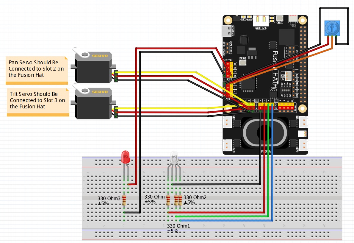
In this lesson, we will be adding the SSD1306 OLED display. Keep the schatic above, but now add the OLED display to the breadboard. It should be connected to the Fusion Hat as follows:
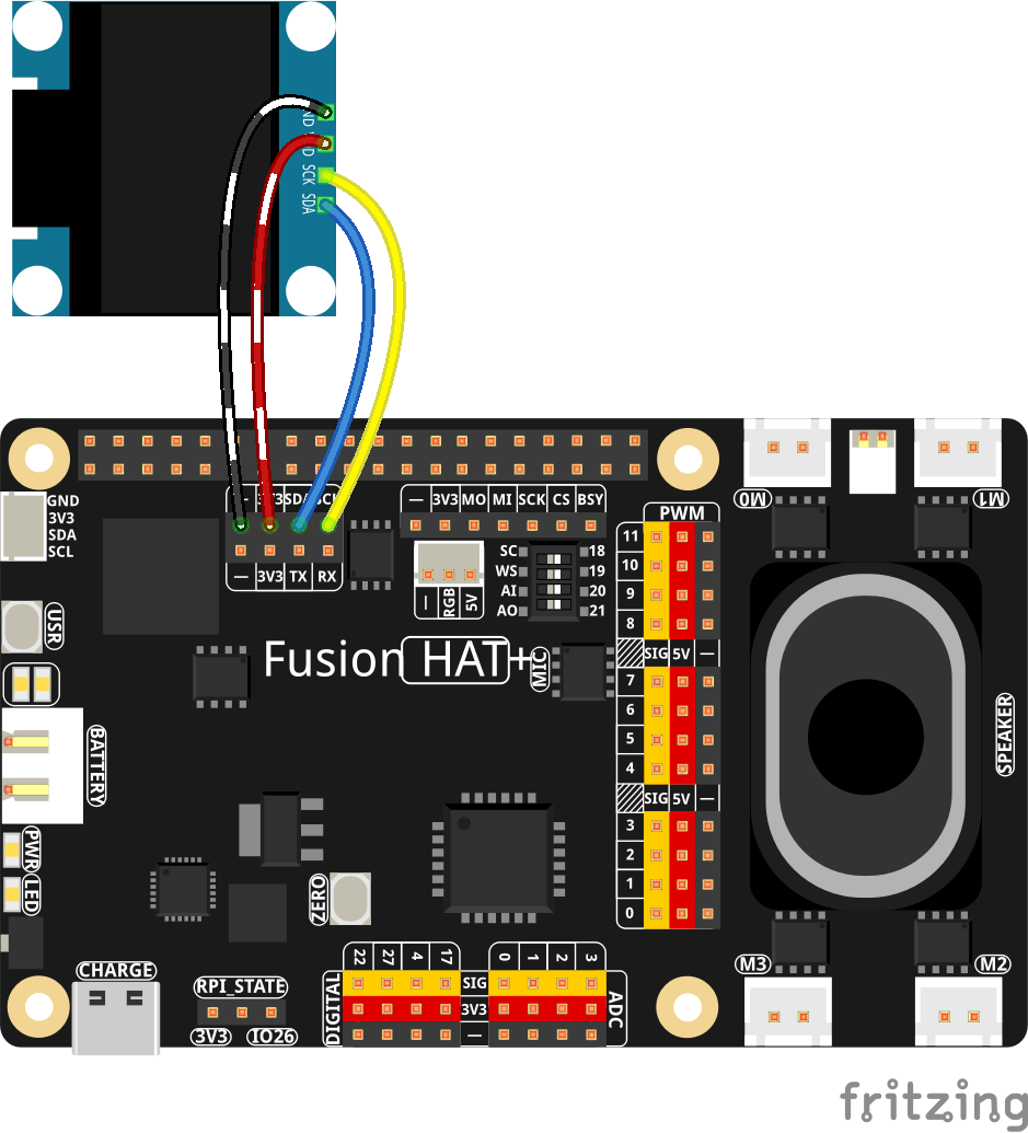
- Connect the VCC pin of OLED display to 3.3V on Fusion HAT+
- Connect the GND pin of OLED display to GND on Fusion HAT+
- Connect the SCL pin of OLED display to SCL (GPIO 3) on Fusion HAT+
- Connect the SDA pin of OLED display to SDA (GPIO 2) on Fusion HAT+
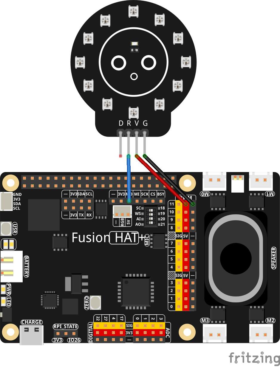
While we are updating our project components, go ahead and connect the neoPixel ring to yout Fusion Hat. Here is the schematic to add the neopixel ring, and we will be using it in future lessons.
In the video, we developed the following code to show you how to put the SSD1306 OLED through its paces using the Fusion AI Hat on the Raspberry Pi 5.
|
1 2 3 4 5 6 7 8 9 10 11 12 13 14 15 16 17 18 19 20 21 22 23 24 25 26 27 28 29 30 31 32 33 34 35 36 37 38 39 40 41 42 43 44 45 46 47 48 49 50 51 52 53 54 55 56 57 58 59 60 61 62 63 64 65 66 67 68 69 70 71 72 73 74 75 76 77 78 79 80 81 82 83 84 85 86 87 88 89 90 |
# ==================================================================== # DISCLAIMER: # This code is provided as-is for educational and experimental # purposes only. The author makes no representations or warranties of # any kind concerning the safety, suitability, or accuracy of this # code. Use at your own risk. The author assumes no liability for any # damages, system failures, security breaches, or network issues # resulting from the use or implementation of this script. # ==================================================================== import board import adafruit_ssd1306 from PIL import Image, ImageDraw, ImageFont import time W =128 H = 64 I2C_ADDRESS = 0x3C i2c = board.I2C() oled = adafruit_ssd1306.SSD1306_I2C(W, H, i2c, addr=I2C_ADDRESS) fontLarge = ImageFont.truetype("/usr/share/fonts/truetype/dejavu/DejaVuSans-Bold.ttf",14) fontMedium = ImageFont.truetype("/usr/share/fonts/truetype/dejavu/DejaVuSans.ttf",10) fontSmall = ImageFont.truetype("/usr/share/fonts/truetype/dejavu/DejaVuSans.ttf",8) image = Image.new("1", (W,H)) draw = ImageDraw.Draw(image) draw.point((int(W/2),int(H/2)), fill =255) oled.image(image) oled.show() ts=1 time.sleep(ts) image = Image.new("1", (W,H)) draw = ImageDraw.Draw(image) draw.text( (0,0), "TopTechBoy.com",font=fontLarge, fill=255) draw.text( (0,16), "SSD1306 OLED",font=fontMedium, fill=255) draw.text( (0,26), "Fusion AI Hat",font=fontMedium, fill=255) draw.text( (0,36), "Hello Makers",font=fontMedium, fill=255) draw.text( (0,46), "Enjoy!",font=fontSmall, fill=255) oled.image(image) oled.show() time.sleep(ts) image = Image.new("1", (W,H)) draw = ImageDraw.Draw(image) draw.rectangle((int(.1*W),int(.1*H),int(.9*W),int(.9*H)), width=5, outline=255, fill=0) draw.text((int(W/4),int(H/2.5)), "Hello World",font=fontMedium, fill=255) oled.image(image) oled.show() time.sleep(ts) image = Image.new("1", (W,H)) draw = ImageDraw.Draw(image) draw.rectangle((int(.1*W),int(.1*H),int(.45*W),int(.45*H)),width=1, outline=255, fill=0) draw.rectangle((int(.55*W),int(.1*H),int(.9*W),int(.45*H)),width=1, outline=255, fill=255) d=25 draw.ellipse((int(.1*W),int(.55*H),int(.1*W)+d,int(.55*H)+d),width=1, outline=255, fill=0) draw.ellipse((int(.55*W),int(.55*H),int(.55*W)+d,int(.55*H)+d),width=1, outline=255, fill=255) oled.image(image) oled.show() time.sleep(ts) xCenter=40 yCenter=25 radius=7 dx = 1 dy = 1 for frame in range(500): image = Image.new("1", (W,H)) draw = ImageDraw.Draw(image) draw.rectangle((0,0,W-1,H-1), width=1, outline = 255, fill=0) draw.ellipse((xCenter-radius,yCenter-radius,xCenter+radius,yCenter+radius), width=1,outline=255,fill=255) #draw.rectangle((0,0,W-1,H-1), width=1, outline = 255, fill=0) oled.image(image) oled.show() xCenter = xCenter + dx yCenter = yCenter + dy if xCenter <= radius or xCenter >= W-1-radius: dx = -dx if yCenter <= radius or yCenter >= H-1-radius: dy = -dy |