Tag Archives: Artificial intelligence

AI on the Edge 38: Using MediaPipe for Face Recognition on the Raspberry Pi 5

In this video lesson we introduce you to MediaPipe. The OS we had you flash in LESSON 1 already has the MediaPipe framework installed, and all the needed and working dependencies. If you have installed that OS and not modified it, this and future lessons will work. If you find dependency errors, you might need to reflash the original OS.

MediaPipe is a free, open-source framework developed by Google that makes it much easier to add advanced computer vision and AI features to your Python programs. It is especially popular among developers who use OpenCV because it works seamlessly with it and delivers excellent real-time performance, even on devices like the Raspberry Pi 5.

With MediaPipe, you can quickly add powerful capabilities such as face detection, face mesh (detailed facial landmarks), hand tracking, body pose estimation, and more — all without having to write complex deep learning code from scratch. It comes with pre-trained machine learning models that are optimized for speed, allowing your programs to run smoothly at 30 frames per second or higher.

The biggest advantage for Python + OpenCV users is its simplicity. You capture video frames using OpenCV or picamera2, pass them to MediaPipe for processing, and then draw the results (such as bounding boxes or landmarks) back onto your image using normal OpenCV functions. This combination gives developers a fast and straightforward way to build interactive computer vision projects like face trackers, gesture-controlled robots, or smart camera applications.

In short, MediaPipe acts as a powerful, easy-to-use toolkit that bridges the gap between OpenCV and modern AI vision technology.

We introduce you to MediaPipe using a simple example where we create a faceFinder on our Raspberry Pi 5.


Local Voice Control of NVIDIA Jetson Orin Nano with STT: Getting Started with Vosk

Engineering Your Own Local Voice Assistant: No Cloud, No Compromise

Most “smart” voice assistants are just glorified remote controls for someone else’s server. Today, we’re changing that. We are going to build a local, offline voice command pipeline. This isn’t just about saving data; it’s about ownership. When you can control your hardware—like opening and closing a farm gate—without an internet connection, you have built a system that is robust, private, and yours to control forever. Today you are going to get Speech to Text up and running on your NVIDIA Jetson Orin Nano running under Jetpack 7.2.

The “Why” Behind the Setup

You might ask, “Why not just use a cloud API?” Because cloud APIs are fragile. They rely on internet stability, external servers, and privacy-invasive data logging. By running Vosk locally, we keep the processing on your hardware (like the NVIDIA Jetson). It’s faster, it works in the middle of a power-isolated homestead, and it’s 100% secure.

Part 1: Preparing the Environment

Before we can make the machine listen, we have to prepare the battlefield. We aren’t just downloading files; we are setting up a stable environment where your dependencies won’t conflict with your OS.

This is IMPORTANT!

Now you can post the code below. You also have to point Thonny to run in the virtual environment. Open Thonny, and under run –  select interpreter. Then you must point it to /home/yourUserName/STT/ttsVenv/bin/python3. For me, my username is pjm, but you put in your user name in path above. Here is what mine looked like:

Part 2: Solving the PipeWire Challenge

The biggest headache in modern Linux audio is PipeWire. If you try to open a microphone stream using a hardcoded sample rate that doesn’t match your hardware, your program won’t just fail—it will segfault. We use the validation script below to programmatically query the hardware, asking it: “What sample rate are you running at?” before we even try to open a stream.

Homework: Your Gate Controller

You now have a system that identifies audio input, resamples it to 16kHz, and outputs text. Your assignment: Transform this text output into an action.

I want you to add a conditional statement to the main loop. If the recognized text is “open”, print an ASCII art representation of an open gate. If it’s “close”, print the closed version. This is the first step in closing the loop between your AI and the physical world. Go get ’em, and don’t just copy the code—understand how the data flows from the microphone to your decision logic!

AI on the Edge LESSON 30: Tune Object Tracker with Mouse Selected ROI

AI on the Edge LESSON 30: Tune Object Tracker with Mouse Selected ROI

Welcome, Makers!

Well, hello there! It is absolutely fantastic to have you back. I’m Paul McWhorter, and today, we are taking a massive step forward in our AI on the Edge journey.

Up until now, we’ve been hard-coding our color thresholds (those pesky Lower Color and Upper Color values) to tell our camera what to look for. That’s fine for a science experiment, but it’s not exactly “smart,” is it? If the lighting changes, or if we want to track a different colored object, we have to go back into the code and manually edit those numbers.

Not anymore!

In today’s lesson, we are building a tool that lets us teach the AI. We’re going to use the mouse to draw a Region of Interest (ROI) right on our camera feed. The system will look at the pixels inside that box, calculate the average Hue, Saturation, and Value, and automatically set our tracking range for us.

This is the kind of professional-level functionality that turns a hobby project into a true, intelligent machine.

The Concept: From Hard-Coding to Dynamic Learning

The magic happens in our mouseAction function. Instead of just reading pixel values, we are now implementing a “click-and-drag” system:

  1. Click and Hold: We capture the startX and startY coordinates.

  2. Drag: We draw a rectangle in real-time so we can see exactly what area we are selecting.

  3. Release: We take that specific slice of the image, convert it to the HSV color space, and use the cv2.mean() function to find the average color properties.

  4. Auto-Tune: We set our LC (Lower Color) and UC (Upper Color) based on that average.

By doing this, the system learns what “object” we want to track on the fly. It’s elegant, it’s powerful, and it feels like real magic when you see those servos snap onto your target after a quick mouse drag.

What We’ve Accomplished

By the end of this lesson, you will have a system that:

  • Visually selects an object using the mouse.

  • Automatically calculates the optimal HSV thresholds for that specific object.

  • Updates the tracking behavior immediately without needing to stop or re-run the code.

  • Maintains that professional “Edge” feel, giving you real-time feedback on your FPS and mouse position data.

A Note on the “Edge”

Remember, we aren’t just running code; we are running on hardware. When we calculate the mean of the ROI, we are doing real image processing on the fly. You’ll notice the Composite and Mask windows updated immediately, giving you a visual confirmation that your “teacher” (you!) has successfully guided the “student” (the AI).

This is the power of working with OpenCV and the Raspberry Pi. You are building a system that observes, thinks, and reacts—all in real-time.

Get Ready to Build

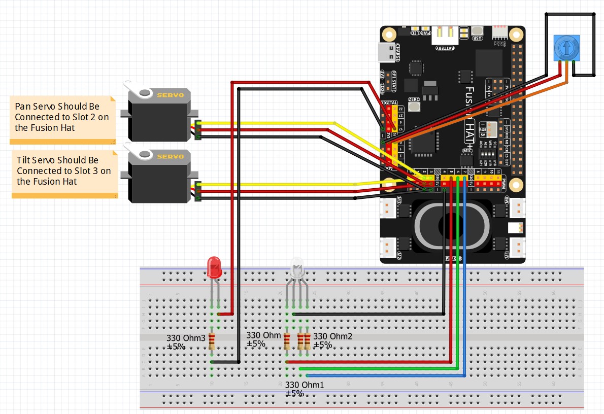
Grab your Pi, make sure your servos are ready to go, and let’s get that camera calibrated. You’ve put in the work to get this far, and today is where all that effort starts to feel really rewarding.

I’m incredibly proud of how far you’ve come. Let’s dive in and start building!

Are you ready to see how accurately your Pi can “see” once you’ve given it the ability to learn from your selections?

In the video lesson we developed the following code.


AI on the Edge LESSON 29: Improved Proportional Object Tracking with Pan Tilt Camera

AI on the Edge LESSON 29: Improved Proportional Object Tracking with Pan Tilt Camera

Hey everyone, Paul McWhorter here from TopTechBoy.com. Welcome back to our channel, where we learn to build real, intelligent systems on edge hardware. Go ahead and grab yourself a nice hot cup of coffee or a big glass of iced tea, because today we are going to completely revolutionize the way our robotic pan-tilt camera interacts with the physical world.

In Lesson 28, we successfully closed the loop. We got our camera to physically move and track an object using the error signal calculated from our OpenCV bounding box. It worked, but let’s be honest with ourselves: it was clunky. It was a crude, incremental system that moved the camera by exactly one lazy degree at a time, regardless of whether the target was right next to the crosshairs or flying across the room. It was jerky, it hunted back and forth, and it just wasn’t elegant old-school engineering.

Today, we are throwing away that clunky incremental logic and replacing it with something beautiful: Proportional Control.

The Problem with Lazy Incremental Steps

Before we fix our control loop, we need to understand exactly why our previous system struggled. In our last script, we used conditional statements to see if the error was positive or negative, and then adjusted our angles by a fixed step of 1 or -1.

This created two major engineering flaws:

  • Lagging on Large Errors: If you suddenly jerked the object 400 pixels away from the center, the camera would take forever to catch up because it could only step at a constant speed of one degree per loop iteration.

  • Hunting and Jitter on Small Errors: When the object finally got close to the center, the camera would overshoot by a full degree, trip the opposite condition, and step back. It would constantly “hunt” back and forth across the target, buzzing your hardware to pieces.

The Elegance of Proportional Control

In real-world automation, we don’t use rigid, conditional step-programming to move hardware. We use mathematics. We want the camera’s reaction to be completely proportional to the size of the mistake it is trying to correct.

If the object is a massive distance away from the center crosshairs, we want the servo to take a massive, aggressive leap to catch up instantly. As the object gets closer and closer to the center, we want the camera to automatically slow down and gently glide into place. When the error drops to zero, the physical adjustment should naturally drop to zero.

The magic of this approach is that it allows us to completely eliminate the bulky conditional statements and artificial deadbands we wrote last time. The algebra naturally handles the direction and magnitude of the movement.

Breaking Down the Math and Logic

To achieve this fluid motion, we take our raw error signal—the distance in pixels between our frame center and the object center—and apply a scaling factor, known in control theory as Gain.

In this updated system design, we take our error and divide it down. Specifically, we divide the pixel error by 50, and then split that in half by dividing by 2. Mathematically, this means we are scaling our pixel error down by a factor of 100.

  • If your object is 300 pixels off-center, the math calculates an instantaneous adjustment of 3 degrees, quickly snapping the camera toward the target.

  • If the object is only 10 pixels off-center, the adjustment becomes a tiny fraction of a degree (0.1), smoothly stabilizing the camera track.

Precision Tracking with Floating-Point Variables

Because we are dividing our pixel error down by 100, our angular adjustments will almost always be fractional decimals rather than clean integers. If we tried to store these angles as standard integers, our program would truncate those decimals, completely throwing away our precise micro-adjustments and causing the camera to stall out.

To make this system work perfectly, we maintain our accumulation variables as high-precision floating-point numbers. The script constantly adds and subtracts these fractional updates over time behind the scenes. We only cast the final calculated angle to a clean, rounded integer at the absolute last microsecond right as we pass the position command to the physical servo motors.

Visual Tuning and Smooth Performance

You will notice a massive visual upgrade when running this refined loop. To match our new high-precision math, we tighten up our tracking reticle overlay, shrinking our target circle down from a radius of 40 to a crisp 30 pixels. We also change our dynamic bounding box to a bright, vibrant yellow to make our tracking visually pop on screen.

When you fire up this loop and wave your object around, you will see a night-and-day difference compared to last week. The lazy, robotic stutter is completely gone. The pan-tilt mount tracks with an organic, fluid motion, actively accelerating and decelerating to mirror your movements perfectly.


NVIDIA Jetson Orin Nano: Secret to Running Ollama on the GPU

One of the biggest frustrations with the new Jetpack 7.2 release is finding out that a standard installation of Ollama—the gold standard for running local LLMs—completely ignores your powerful NVIDIA GPU and defaults to the CPU.

In this lesson, we aren’t just going to fix that; we are going to measure the “truth” behind the performance. We will use data to see exactly how much gain we get from the GPU and where the hardware starts to hit the thermal throttling wall.

The Problem: The “Canned” Installation

When you run a standard Ollama install on the Jetson Orin Nano, the system doesn’t automatically recognize the integrated GPU (iGPU). If you open your NVIDIA Power GUI (jtop), you will see your CPU cores pegged at 100% while the GPU sits idle. This leads to slow response times and a disappointing experience.

Lets start by the standard ‘Canned’ Installation. The good news is, it is very simple:

To see exactly how your system is performing, run Ollama in verbose mode:

At this point you will have Ollama running a simple LLM locally on your Jetson Orin Nano. This is a huge step forward, but we now want to dig deeper and actually see how well this simple model is performing.  The first thing we do is run the Jetson Power GUI, hidden behind the NVIDIA icon in upper right of the menu bar.

Pay close attention to the Prompt Eval Rate and Eval Rate (tokens per second). These are our baseline numbers.

The “Secret Sauce” Solution

To force Ollama to use the Jetson’s CUDA cores, we have to manually override the system service configuration.

Step 1: Install the Nano Editor

Before we can edit system files, we need a reliable text editor. If you don’t have it yet, run this command:

Step 2: Create the Service Override

We need to tell the Ollama service exactly where to look for the GPU libraries. Use nano to open the following file:

Step 3: Add the Configuration

Copy and paste the following block into that file. This is the “Secret Sauce” that enables the iGPU and points the system to the correct CUDA backend:

Note: Save the file by pressing Ctrl+OEnter, and then Ctrl+X to exit.

Step 4: Reboot

For the changes to take effect, We will do a reboot.

Benchmarking the Results

Once you have the GPU engaged, the real work begins. In the video, we look at a side-by-side comparison of performance across different Jetson Power Modes (10W, 15W, and MaxN).

Power Level Prompt Eval Rate (t/s)  Eval Rate (t/s) Throttling Observed?
CPU [Your Data] [Your Data] Yes/No
10W [Your Data] [Your Data] Yes/No
15W [Your Data] [Your Data] Yes/No
MaxN [Your Data] [Your Data] Yes/No

As we discovered, moving to the GPU provides a boost, but it also increases the heat signature. Watch the full video to see the charts and understand which power level provides the best “sweet spot” for stable, long-term AI performance on your Jetson Orin Nano. This is an important first step . . . getting the heavy lifting down to the GPU. Now in future videos we will explore how to get the work done Well on the GPU.