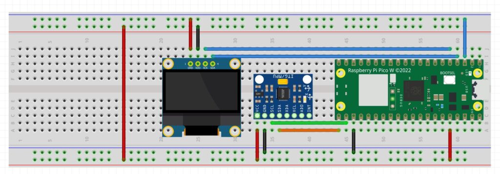
In this video lesson I show you how to use calibrated sensors and Complimentary Filters to perform Sensor Fusion to get high performance IMU data from the GY-87 IMU module. We end up with Roll, Pitch and Yaw that is fast, accurate, low noise, and no drift. The work we do in this lesson uses the calibration data generated in last weeks lesson, if you have not completed that lesson you need to do it before proceeding here. The schematic we are using in this lesson is:

This is the code we developed in this weeks lesson. Note that in the callibrateSensors() function, you need to use the calibration parameters for your module (as explained in last weeks lesson).
1 2 3 4 5 6 7 8 9 10 11 12 13 14 15 16 17 18 19 20 21 22 23 24 25 26 27 28 29 30 31 32 33 34 35 36 37 38 39 40 41 42 43 44 45 46 47 48 49 50 51 52 53 54 55 56 57 58 59 60 61 62 63 64 65 66 67 68 69 70 71 72 73 74 75 76 77 78 79 80 81 82 83 84 85 86 87 88 89 90 91 92 93 94 95 96 97 98 99 100 101 102 103 104 105 106 107 108 109 110 | #include <Adafruit_MPU6050.h> #include <Adafruit_Sensor.h> #include <Wire.h> #include <QMC5883LCompass.h> float AxRaw,AyRaw,AzRaw,GxRaw,GyRaw,GzRaw,MxRaw,MyRaw,MzRaw; float AxCal,AyCal,AzCal,GxCal,GyCal,GzCal,MxCal,MyCal,MzCal; float rollA,pitchA,yawM,rollC,pitchC,yawC; float rollG = 0; float pitchG =0 ; float yawG = 0; float deltaRoll = 0; float deltaPitch = 0; float deltaYaw = 0; float alpha = .1; int tStart =millis(); Adafruit_MPU6050 mpu; QMC5883LCompass compass; void setup() { // put your setup code here, to run once: Serial.begin(115200); mpu.begin(); mpu.setI2CBypass(true); compass.init(); mpu.setGyroRange(MPU6050_RANGE_1000_DEG); delay(100); } void calibrateSensors() { const float axOffset = 0.45407887789180545; const float ayOffset = 0.09432915233553185; const float azOffset = -0.4614157209191969; const float axScale = 0.10141341897341144; const float ayScale = 0.10141341897341144; const float azScale = 0.10141341897341144; const float gxOffset = -2.277507235645022; const float gyOffset = 0.8794902155258137; const float gzOffset = -0.5729577951308232; const float mxOffset = -103.48885017294003; const float myOffset = -96.80085481152321; const float mzOffset = 923.8042898128733; const float mxScale = 0.001156333898601669; const float myScale = 0.001012882116988885; const float mzScale = 0.0009400860982065997; AxCal = (AxRaw - axOffset) * axScale; AyCal = (AyRaw - ayOffset) * ayScale; AzCal = (AzRaw - azOffset) * azScale; GxCal = GxRaw*180/PI - gxOffset; GyCal = GyRaw*180/PI - gyOffset; GzCal = GzRaw*180/PI - gzOffset; MxCal = (MxRaw - mxOffset) * mxScale; MyCal = (MyRaw - myOffset) * myScale; MzCal = (MzRaw - mzOffset) * mzScale; } void loop() { // put your main code here, to run repeatedly: compass.read(); sensors_event_t a, g, temp; mpu.getEvent(&a, &g, &temp); AxRaw = a.acceleration.x; AyRaw = a.acceleration.y; AzRaw = a.acceleration.z; GxRaw = g.gyro.x; GyRaw = g.gyro.y; GzRaw = g.gyro.z; MxRaw= compass.getX(); MyRaw= compass.getY(); MzRaw= compass.getZ(); calibrateSensors(); rollA = atan2(AyCal,sqrt(AzCal*AzCal + AxCal*AxCal))*180/PI; pitchA = atan2(AxCal,sqrt(AzCal*AzCal + AyCal*AyCal))*180/PI; deltaRoll = GxCal*(millis()-tStart)/1000.; deltaPitch = -GyCal*(millis()-tStart)/1000.; deltaYaw = -GzCal*(millis()-tStart)/1000.; tStart = millis(); rollG = rollG + deltaRoll; pitchG = pitchG + deltaPitch; yawG = yawG + deltaYaw; yawM = atan2(MyCal,MxCal)*180./PI; rollC = alpha*(rollA) + (1-alpha)*(rollC+deltaRoll); pitchC = alpha*(pitchA) + (1-alpha)*(pitchC+deltaPitch); yawC = alpha*(yawM) + (1-alpha)*(yawC + deltaYaw); // Serial.print("yawC:");Serial.print(yawC);Serial.print(','); // Serial.print("yawM:");Serial.print(yawM);Serial.print(','); // Serial.print("yawG:");Serial.print(yawG);Serial.print(','); // Serial.print("LL:");Serial.print(-90);Serial.print(','); // Serial.print("UL:");Serial.println(90); Serial.print("rollC:");Serial.print(rollC);Serial.print(','); Serial.print("pitchC:");Serial.print(pitchC);Serial.print(','); Serial.print("yawC:");Serial.print(yawC);Serial.print(','); Serial.print("LL:");Serial.print(-90);Serial.print(','); Serial.print("UL:");Serial.println(90); delay(100); } |