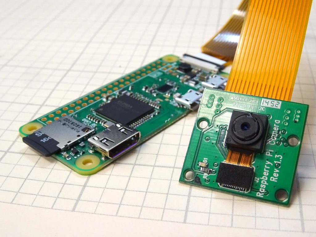
This is a super cool project where we build a concealable, portable, live streaming IP camera based on the Raspberry Pi Zero Model W, and the Raspberry Pi camera module. In order to do this lesson, you need to start with Lesson 1, where we show you how to get the IP address of your Pi zero, and how to get it booted. For this project, you need a Raspberry Pi Zero Model W. If you do not have one, you can get the ESSENTIAL HARDWARE HERE. In addition, you will need the Raspberry Pi Camera, which you can GET HERE. The Pi Zero needs a special Camera Cable, which you can get HERE.
That should be the equipment you need to this really fun project. When you are ready to go, the instructions are in the video below.
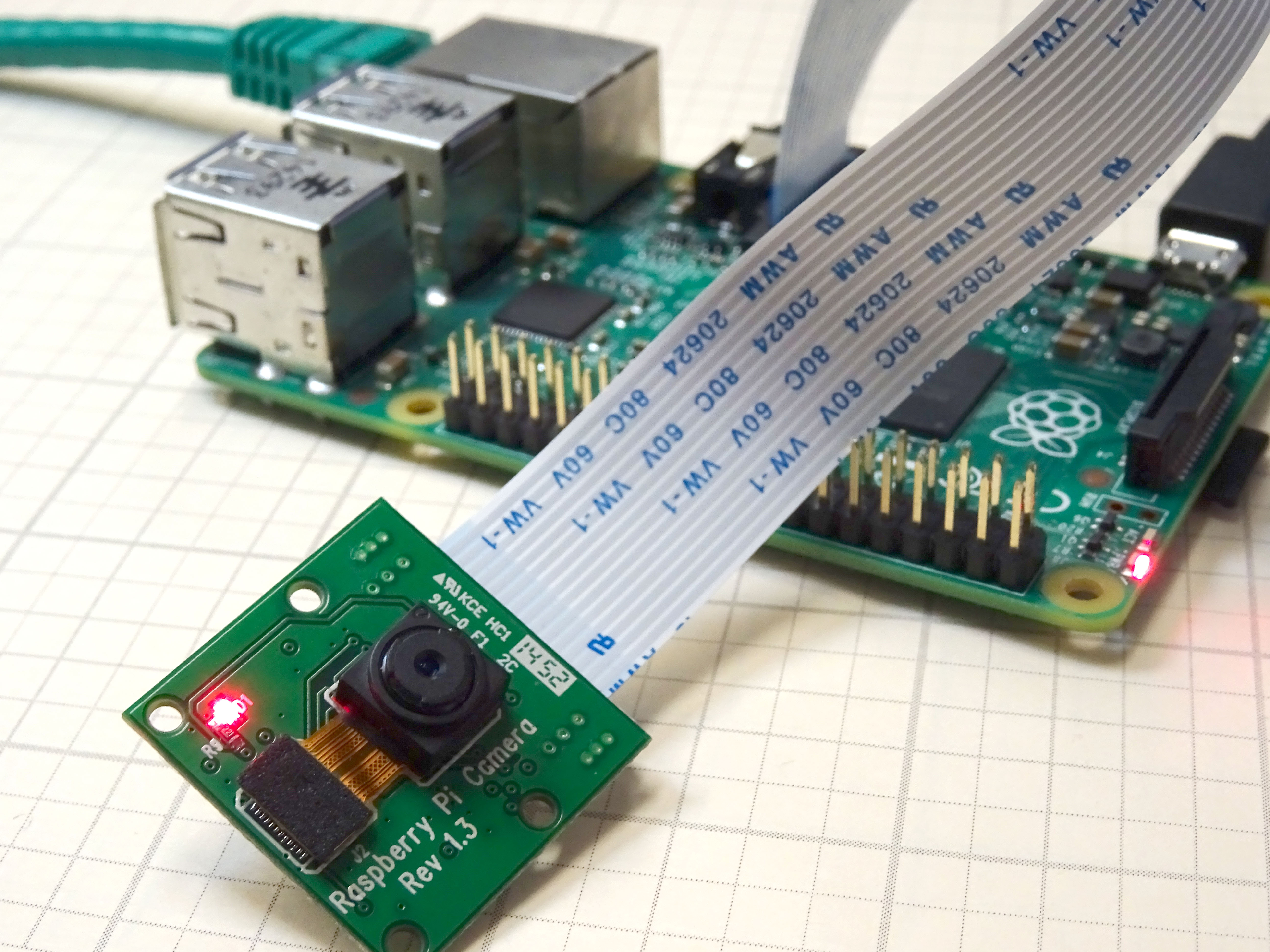
In this lesson we give you a step by step tutorial on how to create a low cost IP camera from a Raspberry Pi and the Raspberry Pi camera module. (If you need to get a Raspberry Pi and Camera Module, we recommend this complete starter Kit, which you can order HERE. If you already have a Raspberry Pi, and just need a camera, you can get the camera module HERE.) We are going to assume you already have your Raspberry Pi up and running, and are able to make a connection to it via Putty or SSH. If you are completely new to the Raspberry Pi, you should probably start with the first two lessons on THIS PAGE.
This video will take you through the steps one at a time. In addition, the tutorial below has the commands that you can copy and paste. We recommend you both follow the video, and get the steps from the instructions below, so you do not have to manually type the commands. Be very careful . . . you must be precise in following these instructions for things to work.
OK, now assuming you have your Raspberry Pi up and running, and you can connect via Putty or SSH, These are the steps to get your dandy personal IP camera working. You will type or copy and paste these lines one at a time into the Raspberry Pi command line.
Now you will want to type or paste this info into the nano window.
Apache
1
<?phpphpinfo();?>
STEP 5: Save your nano file with these key strokes:
Arduino
1
2
3
CtrlO
Enter
CtrlX
To be clear, you press the Control key and the letter “O” at the same time. Then press the enter key. Then press the Control and “X” key at the same time.
STEP 6: Restart the Webserver:
Apache
1
sudo/etc/init.d/lighttpdrestart
STEP 7: Check That the WEB Server is Working:
Go to a browser on a Windows computer on your network, and type:
http://10.1.15.94/
(NOTE: You would use your Pi’s IP address above. The number I use above is the IP address of our Pi. Your number will be different. You can find out your IP address on the pi by typing ifconfig into the terminal window.)
If you configured things correctly, you should get an Apache info page pop up.
Also, you should be able to see your php information page by entering:
http:/10.1.15.94/php.php
Again, you should use your IP address. If you did things correctly you should have a page come up with lots of tables describing php configuration
To be clear, you press the Control key and the letter “O” at the same time. Then press the enter key. Then press the Control and “X” key at the same time.
STEP 13: Restart crtmpserver
Apache
1
sudo/etc/init.d/crtmpserverrestart
STEP 14: Remove ffmpeg
We need to make sure we have a clean copy of ffmpeg, so safest thing to do is un-install it in case an old version is on your pi.
Apache
1
sudoaptituderemoveffmpeg
STEP 15: Intall Latest git-core and ffmpeg software
# By default, the home directories are exported read-only. Change the
# next parameter to 'no' if you want to be able to write to them.
readonly=yes
# File creation mask is set to 0700 for security reasons. If you want to
# create files with group=rw permissions, set next parameter to 0775.
createmask=0700
# Directory creation mask is set to 0700 for security reasons. If you want to
# create dirs. with group=rw permissions, set next parameter to 0775.
directorymask=0700
# By default, \\server\username shares can be connected to by anyone
# with access to the samba server.
# The following parameter makes sure that only "username" can connect
# to \\server\username
# This might need tweaking when using external authentication schemes
validusers=%S
# Un-comment the following and create the netlogon directory for Domain Logons
# (you need to configure Samba to act as a domain controller too.)
;[netlogon]
;comment=NetworkLogonService
;path=/home/samba/netlogon
;guestok=yes
;readonly=yes
[home]
path=/
public=yes
readonly=no
writeable=yes
browseable=yes
createmask=0777
directorymask=0777
# Un-comment the following and create the profiles directory to store
# users profiles (see the "logon path" option above)
# (you need to configure Samba to act as a domain controller too.)
# The path below should be writable by all users so that their
# profile directory may be created the first time they log on
;[profiles]
;comment=Usersprofiles
;path=/home/samba/profiles
;guestok=no
;browseable=no
;createmask=0600
;directorymask=0700
Now save and exit the nano editor with:
Ctrl O
Enter
Ctrl X
At this point, your Raspberry Pi should show up on your Windows computer network on your windows machine. On your windows machine, open a folder, click on “network” on the left, and you should see your raspberry pi show up. Now you can move files to and from your Raspberry Pi from Windows.
STEP 19: Install Strobe Software and WEB Page:
We will want to be able to view the live video stream in a browser, so we need to install the Strobe software. These next steps will install and enable the strobe feature.
Apache
1
cd/var/www/html
Arduino
1
sudomkdirstrobe
Arduino
1
sudochmod-R777strobe
Now the easiest way to get the strobe software is to download it on a windows computer. You can get the software by going to:
and downloading the latest version of strobe media playback.
Now open the zipped folder and drag and drop the folder “for Flash Player 10.1” to your desktop.
Now move the CONTENTS of the unzipped “for Flash Player 10.1” folder onto your Raspberry Pi. You will want to move the CONTENTS of “for Flash Player 10.1” folder into the /home/var/www/html/strobe folder on your Raspberry Pi. If you installed Samba correctly, the Raspberry Pi should show up when you open a folder in Windows and click on “Network”.
Now you have the strobe software installed and you need to create a Strobe WEB page to display your live video.
First, make sure you are in the html folder by typing:
Apache
1
cd/var/www/html
On your raspberry pi, now issue the command:
Apache
1
sudonanoindex.html
Now paste this code into your Nano window. You can paste by copying the code below, and then going to your Raspberry Pi command Window, and right mouse clicking.
JavaScript
1
2
3
4
5
6
7
8
9
10
11
12
13
14
15
16
17
18
19
20
21
22
23
24
25
26
27
28
29
30
31
32
33
34
35
36
37
38
39
40
41
42
43
<!DOCTYPE html PUBLIC"-//W3C//DTD XHTML 1.0 Strict//EN""http://www.w3.org/TR/xhtml1/DTD/xhtml1-strict.dtd">
Now you should save and exit nano with these commands:
Arduino
1
2
3
CtrlO
Enter
CtrlX
To be clear, you press the Control key and the letter “O” at the same time. Then press the enter key. Then press the Control and “X” key at the same time.
STEP 20: Enable Raspbery Pi Camera Module:
At the command line enter:
Apache
1
sudoraspi-config
Scroll down and enable the camera.
STEP 21: Start the Camera:
You are now ready to fire up the camera. You can start the camera by issuing this command in the Raspberry Pi command window.
One of the things that surprised me about the Beaglebone Black is that it does not come with any simple, direct way to transfer files back and forth with a PC. For our GPS project, we will need to transfer our logged GPS data from the Beaglebone Black to the PC. What I have found is the easiest way to transfer files is using WINscp. You can download this software at:
http://winscp.net/eng/download.php
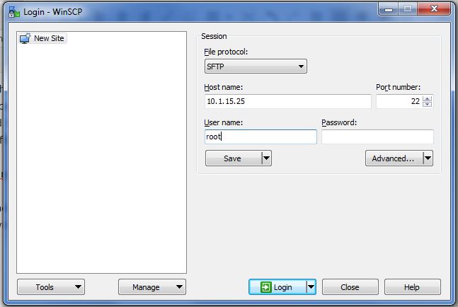
Download and install the software, which takes just a few minutes. One downloaded, launch the program. You will see a window like this:
Login Screen for WINscp
Under host name, you will want to put the IP address of your Beaglebone Black. If you do not know the IP address, we explain how to get it in LESSON 2.
For the default Beaglebone Black configuration, the username is root, and there is no password. Fill in these blanks, and then click “Login”.
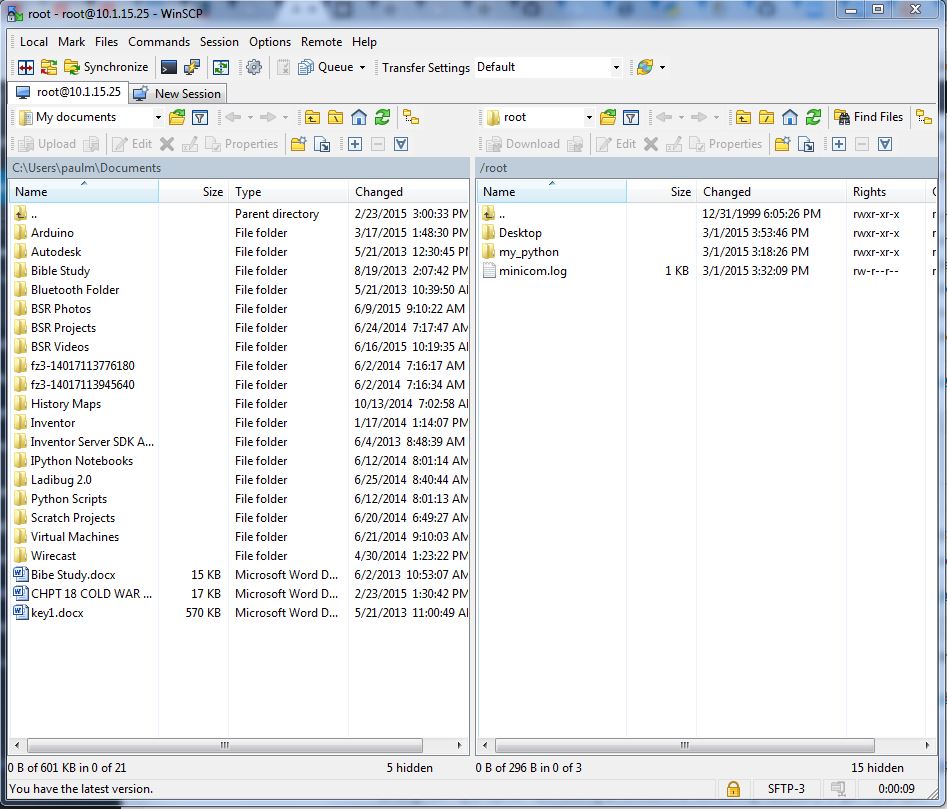
That should take you to this screen:
WINscp Dashboard
At this point the right panel is a view of your Beaglebone Black files. You can navigate by clicking on the folders. An the left is your PC files. You can drag and drop files between the two panels to transfer them to and from the PC and Beaglebone Black.
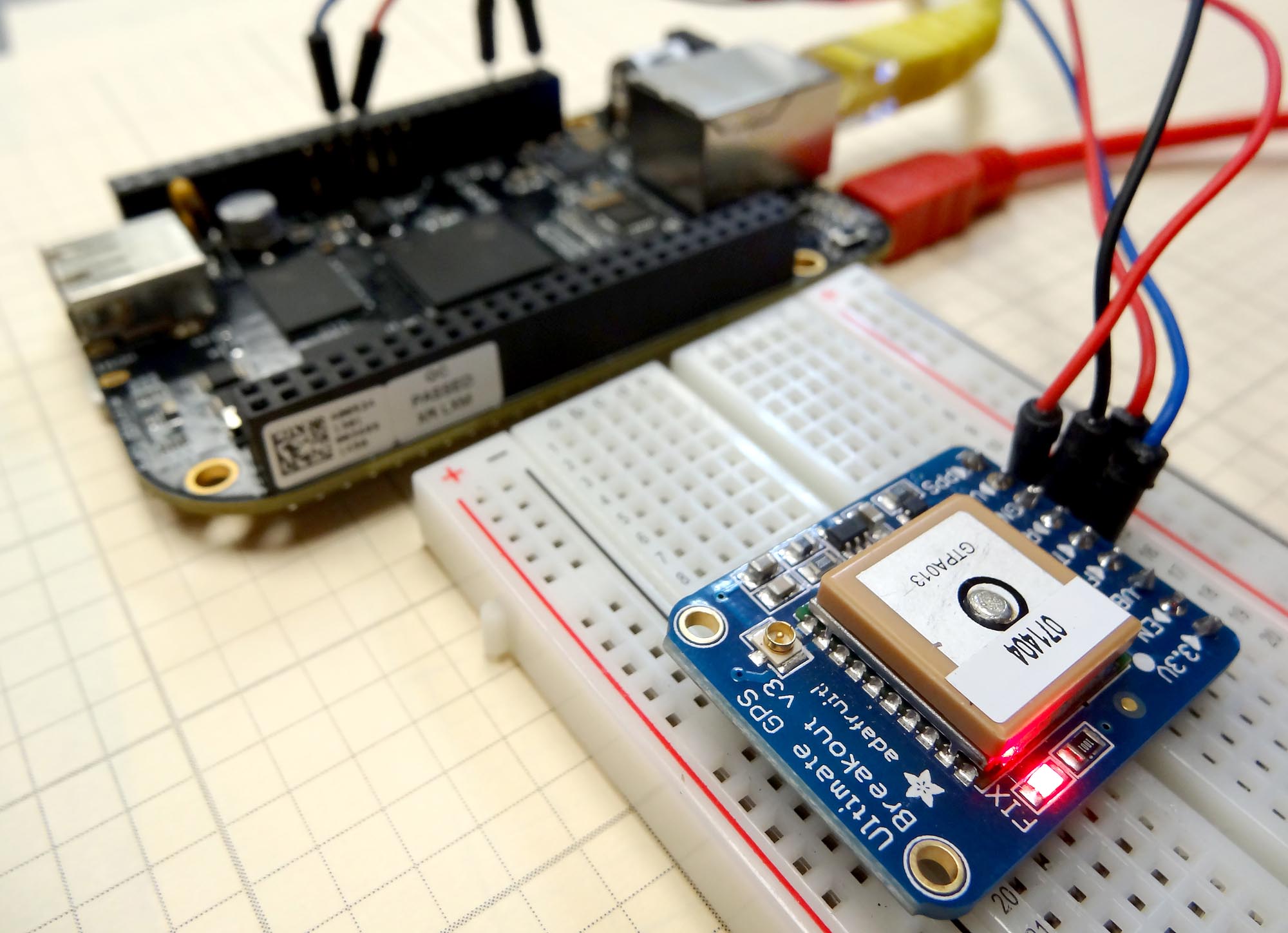
Beaglebone Black connected to the Adafruit Ultimate GPS
In the first two lessons in this series, you learned how to hook the Beaglebone Black to the Adafruit Ultimate GPS breakout board. We then learned to read NMEA sentences from the GPS, and how to control the data the GPS spits out. In this lesson we will learn to parse the NMEA sentences into useful data. You need to make sure you go back and review the first two lessons, as this one draws heavily on those. Also, you need to start with the code we had developed in LESSON 2. (If you need the gear we are using, you can get the Beaglebone Black HERE, and you can get the Adafruit GPS HERE.)
In this code we move most of the work up into our GPS class. That makes the main part of the program simple and intuitive to use.
Python
1
2
3
4
5
6
7
8
9
10
11
12
13
14
15
16
17
18
19
20
21
22
23
24
25
26
27
28
29
30
31
32
33
34
35
36
37
38
39
40
41
42
43
44
45
46
47
48
49
50
51
52
53
54
55
56
57
58
59
60
61
62
63
64
65
66
67
68
69
70
71
72
73
74
75
76
77
78
79
80
81
82
83
84
85
86
87
88
importserial
importAdafruit_BBIO.UART asUART
fromtimeimportsleep
UART.setup("UART1")
ser=serial.Serial('/dev/ttyO1',9600)
classGPS:
def__init__(self):
#This sets up variables for useful commands.
#This set is used to set the rate the GPS reports
UPDATE_10_sec="$PMTK220,10000*2F\r\n"#Update Every 10 Seconds
UPDATE_5_sec="$PMTK220,5000*1B\r\n"#Update Every 5 Seconds
UPDATE_1_sec="$PMTK220,1000*1F\r\n"#Update Every One Second
UPDATE_200_msec="$PMTK220,200*2C\r\n"#Update Every 200 Milliseconds
#This set is used to set the rate the GPS takes measurements
MEAS_10_sec="$PMTK300,10000,0,0,0,0*2C\r\n"#Measure every 10 seconds
MEAS_5_sec="$PMTK300,5000,0,0,0,0*18\r\n"#Measure every 5 seconds
MEAS_1_sec="$PMTK300,1000,0,0,0,0*1C\r\n"#Measure once a second
MEAS_200_msec="$PMTK300,200,0,0,0,0*2F\r\n"#Meaure 5 times a second
#Set the Baud Rate of GPS
BAUD_57600="$PMTK251,57600*2C\r\n"#Set Baud Rate at 57600
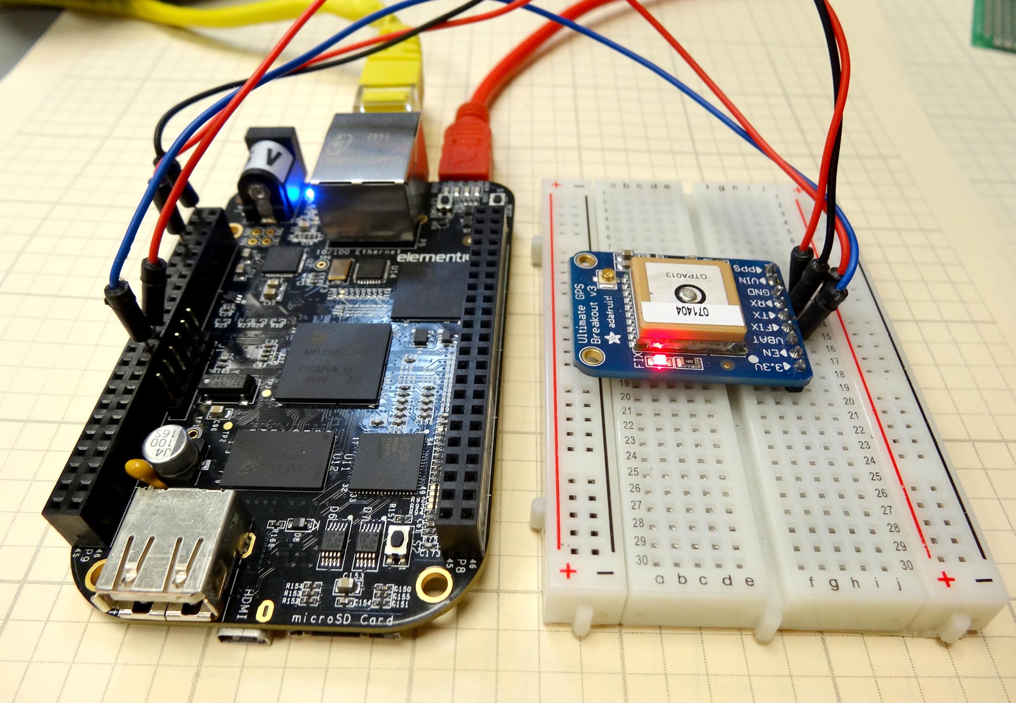
Adafruit Ultimate GPS Connected to the Beaglebone Blak
In lesson 1 we showed you how to connect the Adafruit Ultimate GPS breakout board to the Beaglebone Black and how to read the NMEA sentences streaming off the GPS over the UART pins. In this lesson we will show you how to send commands to the GPS to better tailor its operation for our needs. There are a number of commands that can be sent to it. Some of the things we we can control are the baud rate it communicates at, and the rate that it takes and sends data. We can also influence which NMEA sentences it sends. In this video we will go over the different commands we can use.
To review, you should connect the GPS as follows:
Adafruit Ultimate GPS connected to the Beaglebone Black Rev C Microcontroller
The video explains the code step-by-step, but here it is for your reference.
ser.baudrate=57600#IMPORTANT Since change ser baudrate to match GPS
ser.write(UPDATE_200_msec)#Set update rate
sleep(1)
ser.write(MEAS_200_msec)#Set measurement rate
sleep(1)
ser.write(GPRMC_GPGGA)#Ask for only GPRMC and GPGGA Sentences
sleep(1)
ser.flushInput()#clear buffers
ser.flushOutput()
print"GPS is Initialized"#Print message
myGPS=GPS()
while(1):
ser.flushInput()#Clear Buffers
ser.flushInput()
whileser.inWaiting()==0:#Wait for input
pass
NMEA1=ser.readline()#Read NMEA1
whileser.inWaiting()==0:
pass
NMEA2=ser.readline()
printNMEA1
printNMEA2
This code sets the GPS to communicate at baud rate of 57600, and set it to read and report 5 readings a second. It then sets the GPS to only report the $GPRMC and the $GPGGA sentences. It then constantly reads and reports the NMEA sentences.
Making The World a Better Place One High Tech Project at a Time. Enjoy!