All posts by admin

Beaglebone LESSON 8: Read Button State from Python


In this tutorial we will see how to read digital values from the GPIO pins. We will be doing digital reads, which means we will be limited to “HIGH” or “LOW” readings. This is a 3.3 volt system, so we need to make sure that the “HIGH” applied signal is 3.3 volts.

Our pinout from LESSON 1 shows which pins are suitable for digital reads.

Default Pin Configuration for the Beaglebone Black Rev. C.

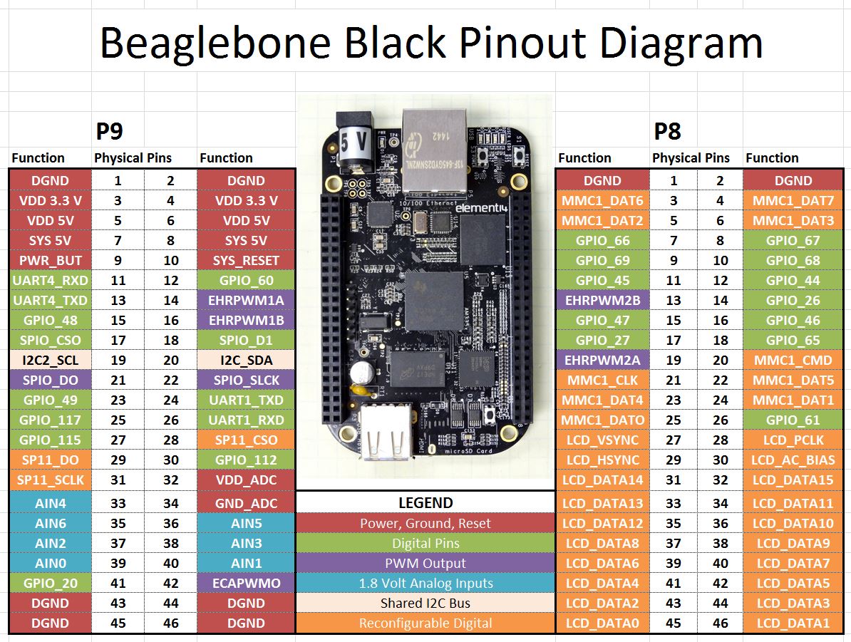
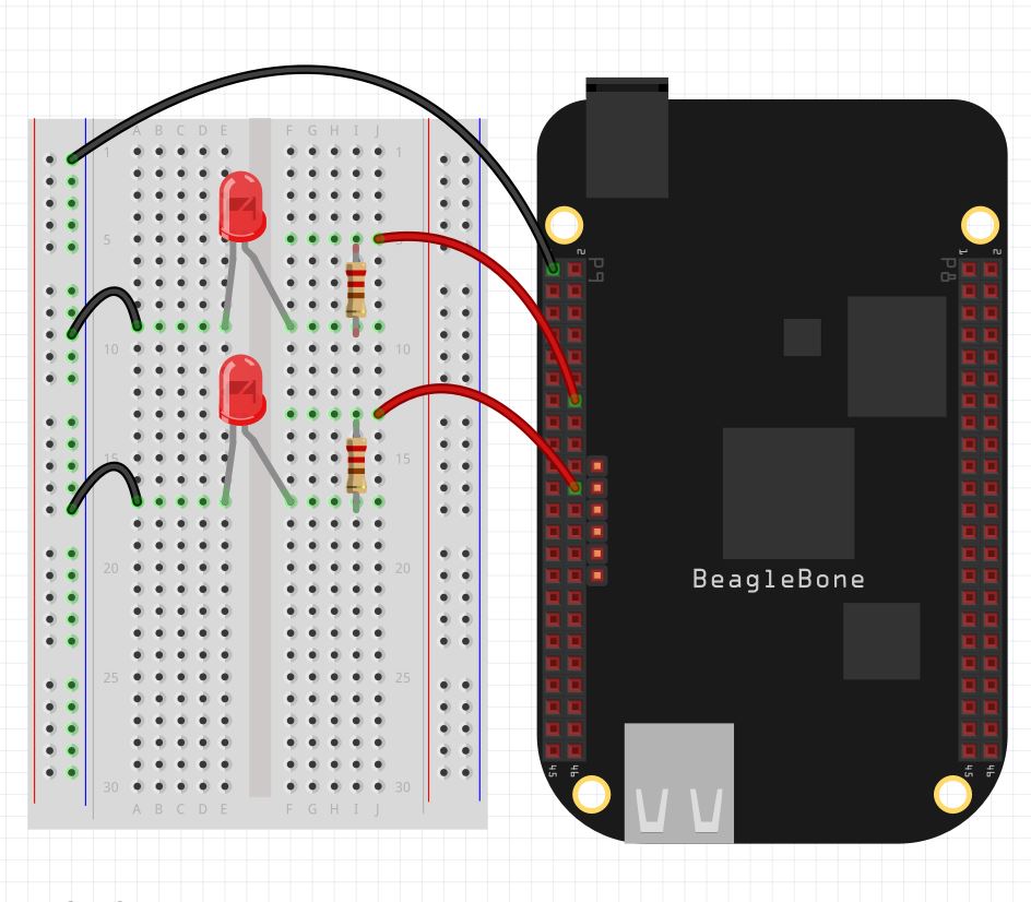
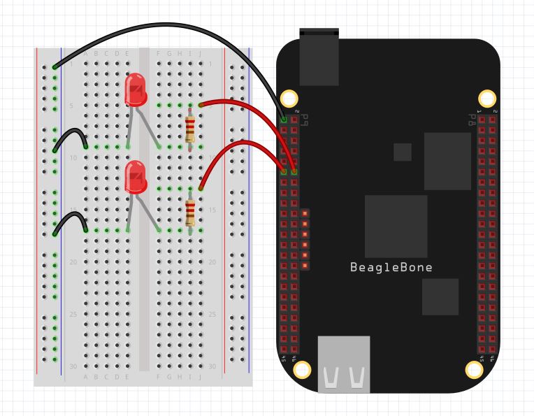
It is the green GPIO pins which we can use for digital reads. In this lesson we will demonstrate the digital read technique using a simple two button circuit. In order to complete this lesson, you should go ahead and build this circuit.

Example of Simple Beaglebone Black Button Circuit

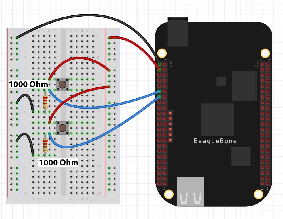
Notice we are using Pin 1 on Header P9 as the ground and Pins 11 and 13 on header P9 s the input pins. Also note the pulldown resistors are 1000 Ohm. It is important to use at least this much resistance. If you do not have 1,000 Ohm resistors, using something larger NOT something smaller.

Once you have the circuit set up we are ready to begin programming.

First up, you need to import the GPIO library. If you have the latest version of Debian Wheezy, you should have the library on your system. If you do not have it you will need to update and upgrade your operating system. To load the library, you will use the python command:

We now need to configure out pins P9_11 and P9_13 as inputs. We do this with the command:

Now to read the state of the buttons, we would use the commands:

state1 will be True if the top button is pushed, and False if it is not being pushed. Similarly, state2 will be True when the button is being pushed, and False when it is not being pushed.

We can bring these concepts together to make the following program. Play around with the program and see what all you can make it do.


Beaglebone Black LESSON 7: Create a Dimable LED Circuit with PWM in Python

In this lesson we will explore how to use the PWM commands we learned in the last lesson to control the brightness of LEDs in a circuit. (If you do not have a Beaglebone Black yet, you can pick one up HERE.) In order to proceed with this project, you should hook the following circuit up to your Beaglebone Black.

This Circuit is Used to Demonstrate a Dimable LED Project

Note that we are using pins “P9_14” and “P9_22” which are good working PWM pins. Note the current limiting resistors are 330 ohm. Always connect the long leg of the LED towards the control voltage.

The video steps you through the code to control the LED brightness.

Beaglebone Black LESSON 6: Control PWM Signals on Output Pins from Python

In Lesson 4 and Lesson 5 we showed how to do digital writes to the GPIO pins using Python. (If you have not picked up your Beaglebone Black Rev. C yet, you can get one HERE) With digital writes, we could generate an output of 3.3 volts or 0 volts. For many applications, we would like analog output, or the in between voltages. The Beaglebone Black, as with most microcontrollers, can not produce true analog output. However, for many applications, an analog output can be simulated by creating a fast on/off sequence where the analog value is simmulated by controlling the ratio of on time and off time. This technique is called Pulse Width Modulation, or more simply, PWM. Consider a 3.3 volt signal, which is turning on and off with a frequency of 50 Hz.  A 50 Hz signal has a Period of: Period=1/frequency=1/50=.02 seconds, or 20 milliseconds. If during that 20 millisecond period, the signal was “High” for 10 milliseconds, and “Low” for 10 milliseconds, the signal would act like a 1.65 volt analog signal. The output voltage therefor could be considered the rail voltage (3.3 volts) multiplied by the duty cycle (percentage of time the signal is high.

For the Beaglebone Black, only certain pins can be used for PWM signals.

Default Pin Configuration for the Beaglebone Black Rev. C.

In the chart above, the purple pins are suitable for PWM output. You can see there are 7 pins which can produce PWM signals. In this lesson we show you how to control those pins.

In order to control PWM signals, we are going to use Python and the Adafruid_BBIO Library. Recent versions of Beaglebone Black Rev. C are shipped with the library already part of the operating system. If you are getting errors indicating that you do not have the library, update your operating system to the latest Debian image for the Beaglebone Black.

In order to use PWM in Python, you must load the Adafruit Library. If you have the recent versions of Debian Wheezy for the Beaglebone black, the library will already be on your system. If you do not do an update and upgrade on your operating system.

To begin with, you will need to load the library.

 Next up, you will need to start the PWM on the pin you are using. We will use pin “P8_13”. Remember you must use one of the purple colored pins on the chart above. We start the PWM with the following command:

This command puts a 1000 Hz signal (Period of 1 mSec) on pin P8_13, with a duty cycle of 25%. This should yield a simulated analog voltage of .84 volts.

We can change the duty cycle after this initial setup with the command:

This command would change the duty cycle to 90%, which would simulate a voltage of 3.3 * .9 =  2.97 volts.

You can also change the frequency of the signal using the command:

This would change the frequency to 100 Hz (Period of 10 mSec). Changing the frequency does not really affect the net result of PWM in most applications, although it does matter for many servo applications.

After you are done, you can stop the PWM with the command:

And always remember to clean up after yourself with:

Play around with the Python Program below. Connect a DVM to your Beaglebone Black, and measure the DC voltage at the output pin. The DVM should show your anticipated voltages.

Considering that the simulated analog voltage V=3.365 X Duty Cycle, how would modify the program above to ask the user for the Voltage he desires, and then calculate the duty cycle that would give that voltage. Your assignment is to modify the program above where the user inputs desired voltage, and DC is calculated. Use a DVM to check your results

Beaglebone Black LESSON 5: Blinking LEDs from GPIO Pins

This lesson shows a simple example of how to blink two LEDs from the GPIO pins on the Beaglebone Black. To get going, you will need to hook up the following circuit. (If you have not ordered your Beaglebone Black, you can get one HERE.)

Circuit for Blinking LEDs from Beaglebone Black

Note that the Top LED is connected to Pin “P9_12” and the bottom LED is connected to Pin “P9_11”. We are using 330 ohm current limiting resistors.

The video lesson takes you through several examples of how to blink the LED. Watch the video, and do the examples. Then play around on your own and see what you can make the LEDs do.

Beaglebone Black LESSON 4: Digital Write to the GPIO Pins from Python

In this lesson we show you how to do digital writes to the GPIO pins from python. If you do not already have a Beaglebone Black Rev C, you can order one HERE.

In order to do this lesson, we need to go back and review the pinout diagram from LESSON 1.

Default Pin Configuration for the Beaglebone Black Rev. C.

In Python, we reference pins by first specifying which header we want (P8 or P9) and then which physical Pin. For Example, to specify pin 12 on the left header, we would refer to it as “P9_12”. For digital output, we should use one of the pins above that is shaded green.

To talk to the GPIO pins in Python, we must first import a library. The latest versions of the Beaglebone Black Rev C. are shipping with the library already installed. If you have an earlier version, you need to update to the latest operating system. You can visit the beagleboard.org web site to download the latest operating system. If you get an error when you try and load the library, you know that either you have typed the command in wrong, or you need to update your operating system. In python to import the library you need to include the line:

Once you have imported the library, you then need to setup your pin as an output pin:

Now if you want to set that pin high you can use the command:

To set the pin low you can use the command:

After you are done working with the pin, you should “cleanup” to free the pin up:

These are all the commands you need in order to set the pin “HIGH” or “LOW”. Remember that in the High state, the Beaglebone Black outputs 3.3 Volts.

We can bring things together to make a simple program that will turn the pin on and off in three second intervals. Try and play around yourself with this code. Then try different GPIO pins.