I hope you all will stick with the Arduino lessons I am putting together. They will really lead to some pretty powerful things you can do. Before too long, I will show you how to build an instrument package and send it to space. We have had two successful missions so far. The first one went to 90,000 feet, and the most recent one to 120,000 feet. Our instrument packages have live onboard telemetry and send dozens of channels of data back to the earth. On our last mission we maintained telemetry for over 70 miles. This video describes an overview of the electronics package and telemetry we designed and built for our space probe.
Here is some exciting footage from our mission as the space probe reached its maximum altitude.
In this lesson we will create a circuit and write arduino code to control two LED’s.
You can jump right to the video, or read through the tutorial.
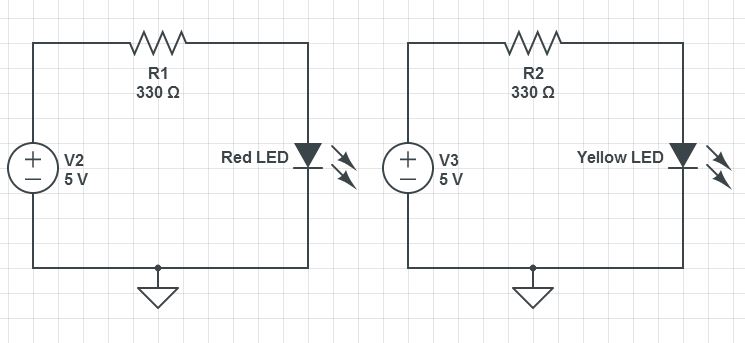
In the earlier lessons we wrote our first programs and built our first circuit. At this time you should be getting comfortable with how the breadboard works and how to work with variables and digitalWrite commands in the arduino IDE (Integrated Development Environment). Now we are going to build a slightly more complicated circuit for controlling two LEDs. Since we want to control each one individually, you will need to have a separate arduino pin control each LED and each LED should have its own current limiting resistor (330 ohms). You should be able to sketch out your own circuit at this point. This is a diagram of the circuit we will be using. Yours does not have to be exactly like this, but it should have the same function.
This circuit will allow you to independently control two Light Emitting Diodes from the arduino microcontroller
Notice that in this circuit, the shorter leg of both LED’s needs to be connected to ground. In order to accomplish this we run a wire from the ground pin on the arduino to the top row of the breadboard. This makes the top row “ground”. Now any device that needs to be grounded can just be connected to the top row, since that row of the breadboard is connected all the way across (See LESSON 1). Also note that both LED’s have their own 330 ohm current limiting resistor, and remember that the direction matters on diodes . . . be sure to put them in with the longer leg connected to the more positive part of the circuit . . . in this case, the longer leg should be connected to the resistor (since the resistor connects to the + voltage coming from the arduino pin).
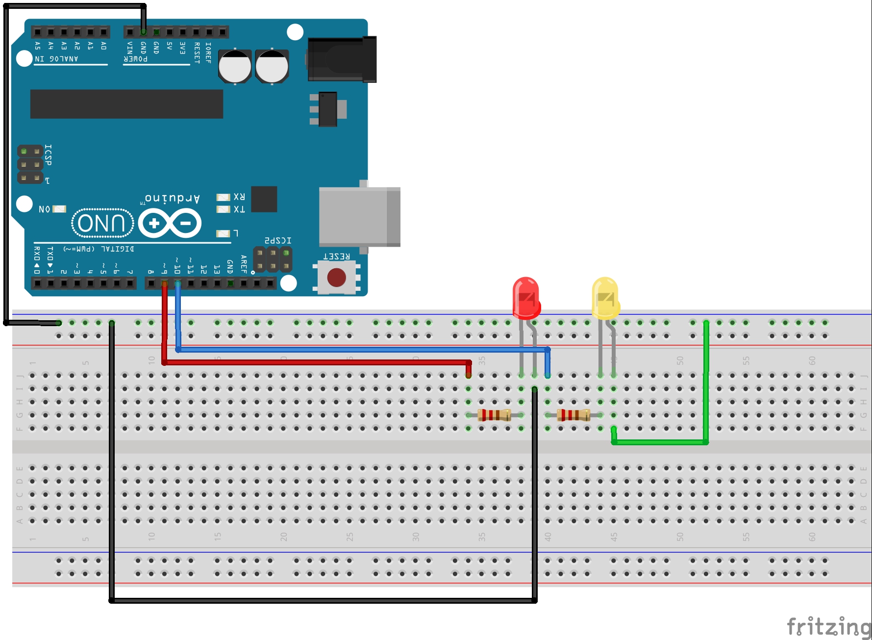
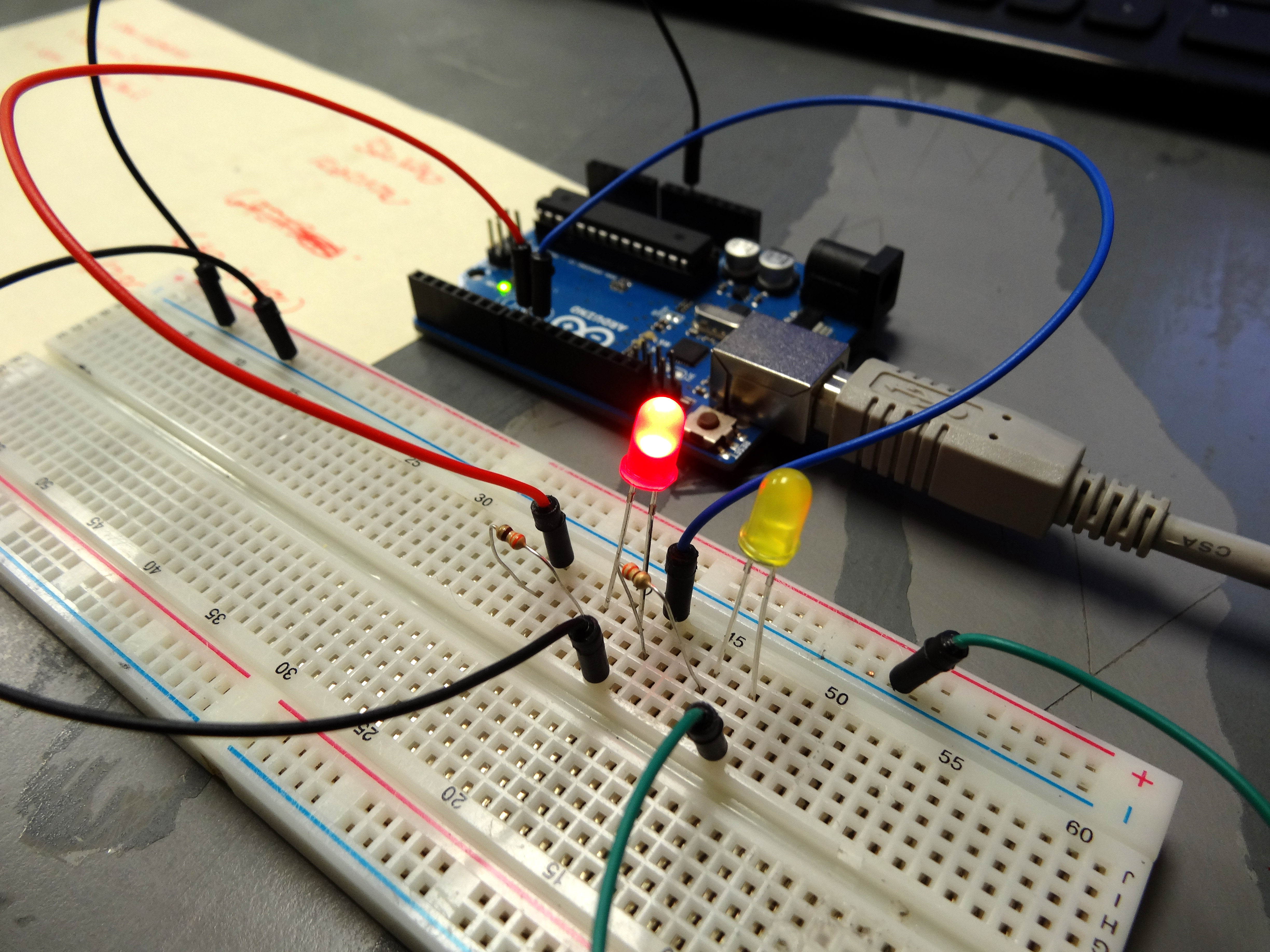
When you get the circuit built, it should look something like this:
Photograph of our Arduino Circuit for Controlling Two Diodes.
Now that your circuit is built, we are ready to do some programming.
Our objective in this exercise is to be able to independently control the LED’s. We will want to blink the red one ten times in a row, and then blink the yellow one once. A “blink” should be turning LED on, leaving it on for a quarter second, turning it off, and leaving it off for a quarter second. Then that sequence will be repeated. So, we will need to think about the variables we will need. We have two LED’s so we will need to declare two variables to indicate the pins that the LED’s are connected to. In the schematic we connected the red LED to pin 9 and the yellow LED to pin 10. Also, since we will be blinking two LED’s, we will need onTime and offTime variables for each LED. You should go ahead and open your arduino IDE and set declare your variables. Think about what you are going to name your variables . . . you do not have to use the same names I use. My code looks like this:
Declare Variables and Assign Values
Arduino
1
2
3
4
5
6
intredLEDPin=9;//Declare redLEDPin an int, and set to pin 9
intyellowLEDPin=10;//Declare yellowLEDPin an int, and set to pin 10
intredOnTime=250;//Declare redOnTime an int, and set to 250 mseconds
intredOffTime=250;//Declare redOffTime an int, and set to 250
intyellowOnTime=250;//Declare yellowOnTime an int, and set to 250
intyellowOffTime=250;//Declare yellowOffTime an int, and set to 250
Now that your variables are declared, what should you do next? That’s right! You need to work on your void setup(). In your void setup you will need to set your pinModes. Since you are using 2 arduino pins this time, you need to issue two pinMode commads as follows.
Do your Void setup
Arduino
1
2
3
4
voidsetup(){
pinMode(redLEDPin,OUTPUT);// Tell Arduino that redLEDPin is an output pin
pinMode(yellowLEDPin,OUTPUT);//Tell Arduino that yellowLEDPin is an output pin
}
Things are moving along and we are now ready to do our main business in the void loop(). Remember our goal is to blink the Red LED ten times, and then blink the yellow LED one time.
Now do the Void Loop
Arduino
1
2
3
4
5
6
7
8
9
10
11
12
13
14
15
16
17
18
19
20
21
22
23
24
25
26
27
28
29
30
31
32
33
34
35
36
37
38
39
40
41
42
43
44
45
46
47
48
49
50
51
52
53
54
55
56
57
58
voidloop(){
digitalWrite(redLEDPin,HIGH);//Turn red LED on
delay(redOnTime);//Leave on for redOnTime
digitalWrite(redLEDPin,LOW);//Turn red LED off
delay(redOffTime);//Leave off for redOffTime
digitalWrite(redLEDPin,HIGH);//Turn red LED on
delay(redOnTime);//Leave on for redOnTime
digitalWrite(redLEDPin,LOW);//Turn red LED off
delay(redOffTime);//Leave off for redOffTime
digitalWrite(redLEDPin,HIGH);//Turn red LED on
delay(redOnTime);//Leave on for redOnTime
digitalWrite(redLEDPin,LOW);//Turn red LED off
delay(redOffTime);//Leave off for redOffTime
digitalWrite(redLEDPin,HIGH);//Turn red LED on
delay(redOnTime);//Leave on for redOnTime
digitalWrite(redLEDPin,LOW);//Turn red LED off
delay(redOffTime);//Leave off for redOffTime
digitalWrite(redLEDPin,HIGH);//Turn red LED on
delay(redOnTime);//Leave on for redOnTime
digitalWrite(redLEDPin,LOW);//Turn red LED off
delay(redOffTime);//Leave off for redOffTime
digitalWrite(redLEDPin,HIGH);//Turn red LED on
delay(redOnTime);//Leave on for redOnTime
digitalWrite(redLEDPin,LOW);//Turn red LED off
delay(redOffTime);//Leave off for redOffTime
digitalWrite(redLEDPin,HIGH);//Turn red LED on
delay(redOnTime);//Leave on for redOnTime
digitalWrite(redLEDPin,LOW);//Turn red LED off
delay(redOffTime);//Leave off for redOffTime
digitalWrite(redLEDPin,HIGH);//Turn red LED on
delay(redOnTime);//Leave on for redOnTime
digitalWrite(redLEDPin,LOW);//Turn red LED off
delay(redOffTime);//Leave off for redOffTime
digitalWrite(redLEDPin,HIGH);//Turn red LED on
delay(redOnTime);//Leave on for redOnTime
digitalWrite(redLEDPin,LOW);//Turn red LED off
delay(redOffTime);//Leave off for redOffTime
digitalWrite(redLEDPin,HIGH);//Turn red LED on
delay(redOnTime);//Leave on for redOnTime
digitalWrite(redLEDPin,LOW);//Turn red LED off
delay(redOffTime);//Leave off for redOffTime
digitalWrite(yellowLEDPin,HIGH);//Turn yellow LED on
delay(yellowOnTime);//Leave on for yellowOnTime
digitalWrite(yellowLEDPin,LOW);//Turn yellow LED off
delay(yellowOffTime);//Leave off for yellowOffTime
}
OK, now you are ready to run your code. If you did it correctly, it should run, and blink the red LED ten times, and then blink the yellow LED one time. If it does not run correctly, you need to debug your code. If it does not work, it is because you made a mistake. Most of the time it is silly typos or forgetting to end lines with a semicolon. Check your work, and you will find your error. Sometimes it helps to have someone else look it over with you.
OK, hopefully you have your code and circuit working now. You can play around with the parameters, and you can see that you can make the LED’s do whatever you want them to.
Now imagine I asked you to make the red LED blink 25 times and then the yellow blink ten times. The problem becomes that it gets very tedious to continue to copy and paste the code, and it eventually becomes impossible to keep track of how many times you have pasted the code in. We need a better way of doing repetitive tasks, like blinking. Luckily there is what is called a “for loop” a for loop will repeat a clause, or a group of commands, or lines of code a specified number of times. The for loop looks like this:
Describe a for loop
Arduino
1
2
3
4
5
for(intj=1;j<=10;j=j+1){
//do something cool in this loop
}
OK, there is lots going on with this new code, so lets break it down. First, notice the open and close curly brackets. All of the code or command lines you put between the curly brackets will be the code that is executed in the for loop. You can put as much or as little code as you want in the for loop. Now lets look at the first line that actually initiates the for loop. Inside the parenthesis are the parameters or arguments that define the behavior of the loop. Notice first that we have introduced a new variable, j. Since we do not need this variable in other parts of the program, we make it a “local” variable. That is, we do not declare it at the top of the program, but declare it just when we use it. That is why we have “int j=1”. The int is declaring that we are going to use a new variable called j. Now j=1 is telling the loop to start with a value of j of 1. Then the j<=10 says to continue to loop as long as j is less than or equal to 10. Then after the next semicolon we have j=j+1. This tells the arduino that each time through the loop, increment j by 1. So, inside the parenthesis we are telling the arduino to start looping with j set equal to one, to continue to loop as long as j is less than or equal to 10, and each time through the loop to add 1 to the value of j.
So, if we want to blink the red LED ten times, it becomes very easy using the following code:
Arduino
1
2
3
4
5
6
for(intj=1;j<=10;j=j+1){// Start our for loop
digitalWrite(redLEDPin,HIGH);//Turn red LED on
delay(redOnTime);//Leave on for redOnTime
digitalWrite(redLEDPin,LOW);//Turn red LED off
delay(redOffTime);//Leave off for redOffTime
}
Remember that our goal was to blink the red LED ten times and blink the yelow LED one time. We need to add a little code so that the LED will blink yellow. This should be done AFTER the for loop.
Arduino
1
2
3
4
5
6
7
8
9
10
11
for(intj=1;j<=10;j=j+1){// Start our for loop
digitalWrite(redLEDPin,HIGH);//Turn red LED on
delay(redOnTime);//Leave on for redOnTime
digitalWrite(redLEDPin,LOW);//Turn red LED off
delay(redOffTime);//Leave off for redOffTime
}
digitalWrite(yellowLEDPin,HIGH);//Turn yellow LED on
delay(yellowOnTime);//Leave on for yellowOnTime
digitalWrite(yellowLEDPin,LOW);//Turn yellow LED off
delay(yellowOffTime);//Leave off for yellowOffTime
WOW, that is a huge improvement over our original code. The for loop makes it much easier to manage things. The one thing that I don’t like about what we did in the code above is that we looped to the constant value of ten. It would be better and smarter to declare a new variable at the top of the program, The new variable could be numRedBlinks. Then in the for loop we would loop until j<=numRedBlinks. Then at the top of the program we could set numRedBlinks to however many times we want the red led to blink.
OK, I have done lots of the work for you in the above example. Now, I want you to write a program where the yellow LED is also controlled inside a for loop. So, you would declare at the top of the program two new variables . . . numRedBlink and numYellowBlink. The program would have a for loop to blink the red LED numRedBlink times, and then blink the yellow LED numYellowBlink times. Good Luck!
RESOURCES USED IN THIS LESSON:
Arduino Microcontroller: You can get a good deal on the arduino on Amazon. Arduinos are open source and many are cheap chinese knockoffs, so you want to make sure you get an “official” version, which you can at the link above.
Sparkfun Inventor’s Kit: While the bare arduino will get you started, I really suggest getting the Sparkfun Inventor Kit. The projects I will feature in this tutorial set will use the components in this kit, and it is probably cheaper to go ahead and get the kit than to buy the individual components as you go along. The kit is under $100 on Amazon.
In this lesson we will begin to build our first circuits that will be controlled by the Arduino. We will start out with simple circuits and build from there. It is important for you to learn the basics before moving on, and one of the most important basics is how to use a Breadboard. In this lesson we will learn the ins and outs of breadboards, and by the end of the lesson you will have your first circuit built, and it will be controlled by the arduino. Watch the video below for in depth description of how the breadboard works.
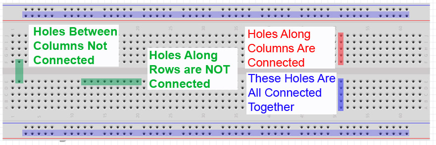
In order to build a circuit, you have to connect circuit elements together. You could run a bunch of wires to connect components, but you find that very quickly you end up with a rats nest of wires, and it becomes impossible to debug. In order to keep your circuit organized you need to use a breadboard, pictured above. The breadboard allows you to connect components together by plugging them into the little holes. The key is to understand how the holes are connected. As you can see in the diagram, the holes in a column (when oriented as shown in the picture) are connected together. So to connect components together you need to plug the leads you want connected into the same column. Note that the columns are not connected across the “trench” in the center of the board. Also notice that as the long rows at the top and bottom are connected together. These are typically used to create “rails”. These are typically used for grounds and supply voltages you might need to connect many components to. Notice some rows are marked (+) and some(-). These are just markings. The row will be set at whatever voltage YOU connect to it.
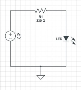
Simple LED Circuit for blinking an LED
So, lets look at a real example. In this circuit we have a voltage supply connected to an LED through a resistor. We will need to take this circuit schematic and figure out how to connect it up in the real world. As mentioned above this should be done using a breadboard. You can see that you need to connect the voltage supply to one leg of the resistor. The other leg of the resistor is connected to the LED. Note that the LED is directional, meaning it has to be connected in a certain orientation. You must connect the Cathode to the positive voltage. The Cathode is typically the longer of the two leads on the LED. If you put the LED in upside down, it will not light up. The other leg of the LED needs to be connected to the negative terminal of the voltage supply. For this project we will supply the voltage from the Arduino microcontroller. That way, we can turn the LED on and off from our program.
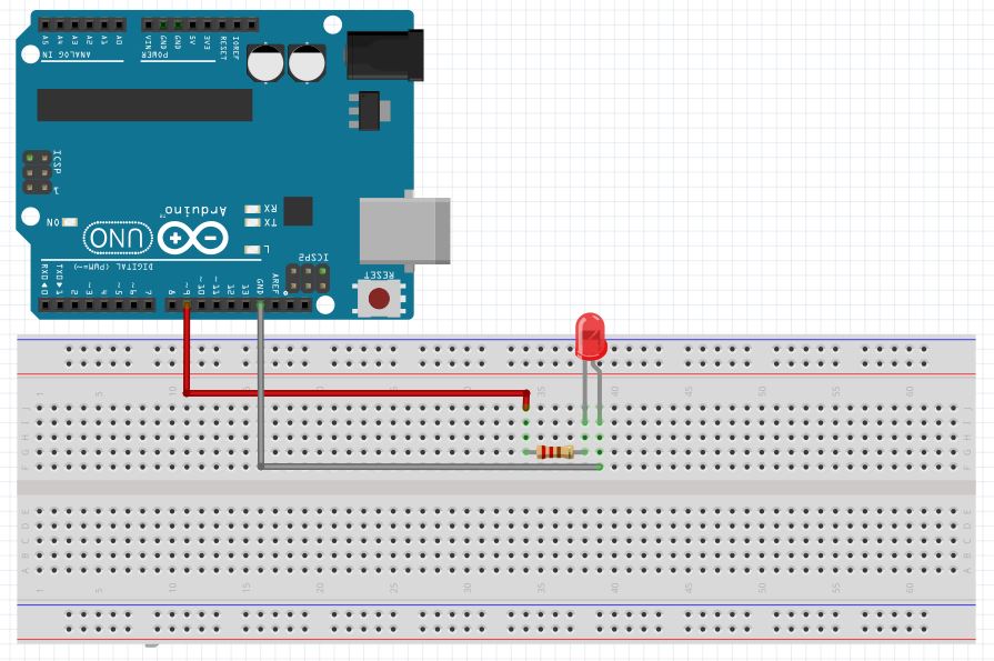
Look at the diagram at the top of this post to see how the holes are connected in the breadboard, and figure out a way you could connect the circuit up using the PC board. There are many ways to hook it up, but one that will work is shown here.
This shows how you can hook an LED to the arduino through a current limiting resistor
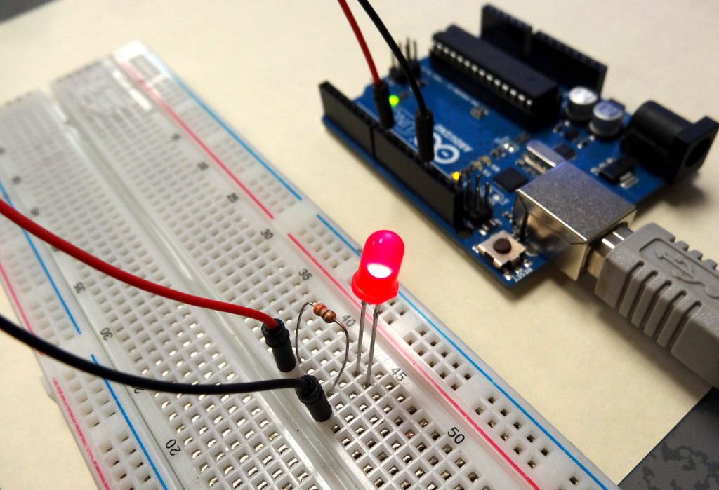
When you hook your circuit up in real life, it should look something like this:
Photograph of the circuit. Your LED will not come on until you write your program
Remember that it is the long leg of the LED that is connected to the resistor and the short leg to the black wire going to ground.
Now, if you follow along and develop the code as outlined in the video you should be able to do amazing things with the LED.
RESOURCES: On all these lessons I will include resources on where you can purchase the items mentioned in the lecture.
Arduino Microcontroller: You can get a good deal on the arduino on Amazon. Arduinos are open source and many are cheap chinese knockoffs, so you want to make sure you get an “official” version, which you can at the link above.
Arduino Beginner’s Kit: While the bare arduino will get you started, I really suggest getting the complete Beginner’s Kit. The projects I will feature in this tutorial set will use the components in this kit, and it is probably cheaper to go ahead and get the kit than to buy the individual components as you go along. The kit is under $100 on Amazon.
I think most people would be amazed at how easy it is to program a microcontroller these days. In this video, I show you step-by-step how to write your first microcontroller program. It is for the Arduiono microcontroller. I chose the arduino because you can buy one for around $20, so you can get started for next to nothing.
RESOURCES: On all these lessons I will include resources on where you can purchase the items mentioned in the lecture.
Arduino Microcontroller: You can get a good deal on the arduino on Amazon. Arduinos are open source and many are cheap chinese knockoffs, so you want to make sure you get an “official” version, which you can at the link above.
Arduino Beginner’s Kit: While the bare arduino will get you started, I really suggest getting the Beginner’s Kit. The projects I will feature in this tutorial set will use the components in this kit, and it is probably cheaper to go ahead and get the kit than to buy the individual components as you go along. The kit is under $100 on Amazon.
I have been playing around with some accelerometers, magnetometers, and gyros. You can do some pretty cool stuff if you get these going and then send the data to Vpython over the serial port. I will be giving more details on this project in future posts, but for now, this video shows some of what is possible. I will be posting code when I get things further along and cleaned up.
Making The World a Better Place One High Tech Project at a Time. Enjoy!