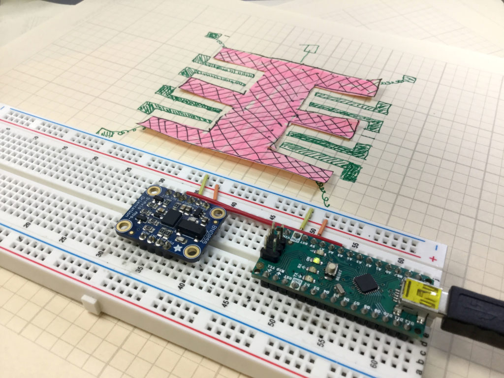
In this lesson we describe how the acceleromters on chips like the Adafruit BNO055 work. They work based on microscopic masses suspended on springs on the chip. As the chip moves, the suspended masses respond to the motion, and the gaps between the suspended masses and the substrate changes. The chips detect these changes in position by monitoring the capacitance between the suspended mass and the substrate, or between the suspended masses and carefully designed interdigitated fingers between the mass and the substrate. C=eA/d, e is the dielectric constant of the material, A is the area of the capacitor, and d is the gap between the two capacitor plates. Changes in measured capacitance come from either a change in A or a change in d. Both d and A change in response to motion, so by monitoring the capacitance of the suspended mass, acceleration can be inferred. The video below explains clearly how this works.
Code for Getting Raw Acceleration Data from the BNO055 9-axis Inertial Measurement Sensor.
The code below is for demo purposes only, and should not be used in any real applications. It just demonstrates how to work with this sensor in benchtop presentations.
1 2 3 4 5 6 7 8 9 10 11 12 13 14 15 16 17 18 19 20 21 22 23 24 25 26 27 28 29 30 31 32 | #include <Wire.h> #include <Adafruit_Sensor.h> #include <Adafruit_BNO055.h> #include <utility/imumaths.h> #define BNO055_SAMPLERATE_DELAY_MS (100) Adafruit_BNO055 myIMU = Adafruit_BNO055(); void setup() { // put your setup code here, to run once: Serial.begin(115200); myIMU.begin(); delay(1000); int8_t temp=myIMU.getTemp(); myIMU.setExtCrystalUse(true); } void loop() { // put your main code here, to run repeatedly: imu::Vector<3> acc =myIMU.getVector(Adafruit_BNO055::VECTOR_ACCELEROMETER); Serial.print(acc.x()); Serial.print(","); Serial.print(acc.y()); Serial.print(","); Serial.println(acc.z()); delay(BNO055_SAMPLERATE_DELAY_MS); } |
