The purpose of this lesson is to assign you homework. Your homework is to create a Bit Flipper. That is, for an 8 bit Binary or Hex number, invert the bits . . . “1” bits should become “0” and “0” bits should become “1”. For example,
if myByte=00001111
the flipped version of this would be
myByteFlipped=11110000
Similarly if myByte=00000001
myByteFlipped=11111110
You could do this with 255 if statements, but see if you can figure out a better way of doing it, and then demonstrate your results using the circuit we have been using in the last few lessons.
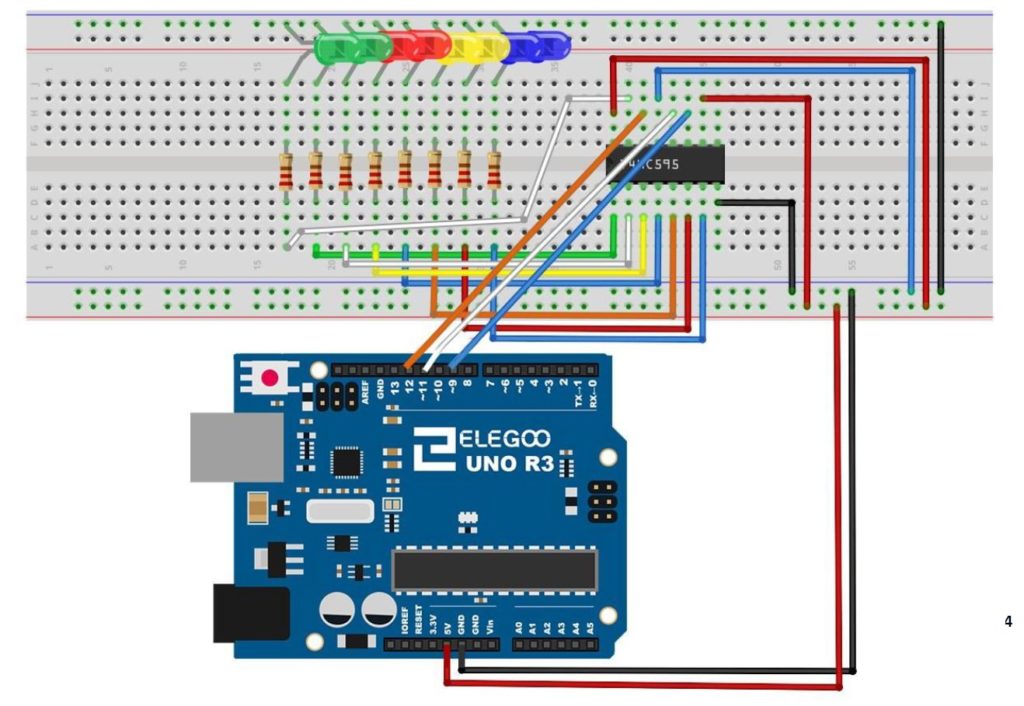
This is the schematic we use in this example to control 8 LEDs from the 74HC595 chip.
In this lesson we develop the initial simple code for leveling the platform. We implement the simplest control system, which is to just increment or decrement the servos based on whether the actual position is greater or less than the target position. We increment/decrement by one degree, since this is the smallest allowed change in servo position. Next week we will implement a more sophisticated control system. Below is the arduino code developed in this lesson.
In this lesson we explore the Circular Shift Left (CSL) and Circular Shift Right (CSR) binary functions. These functions are similar to the Logical Shift Left and Logical Shift Right functions explained in the previous lesson.
As a reminder, we are doing this work on the circuit built in Tutorial 42. As a refresher, we are using the 74HC595 Serial to Parallel converter, connected to an Arduino according to the following schematic.
This is the schematic we use in this example to control 8 LEDs from the 74HC595 chip.
In all these lessons we are using the Arduino Super Starter Kit, which you can pick up HERE.
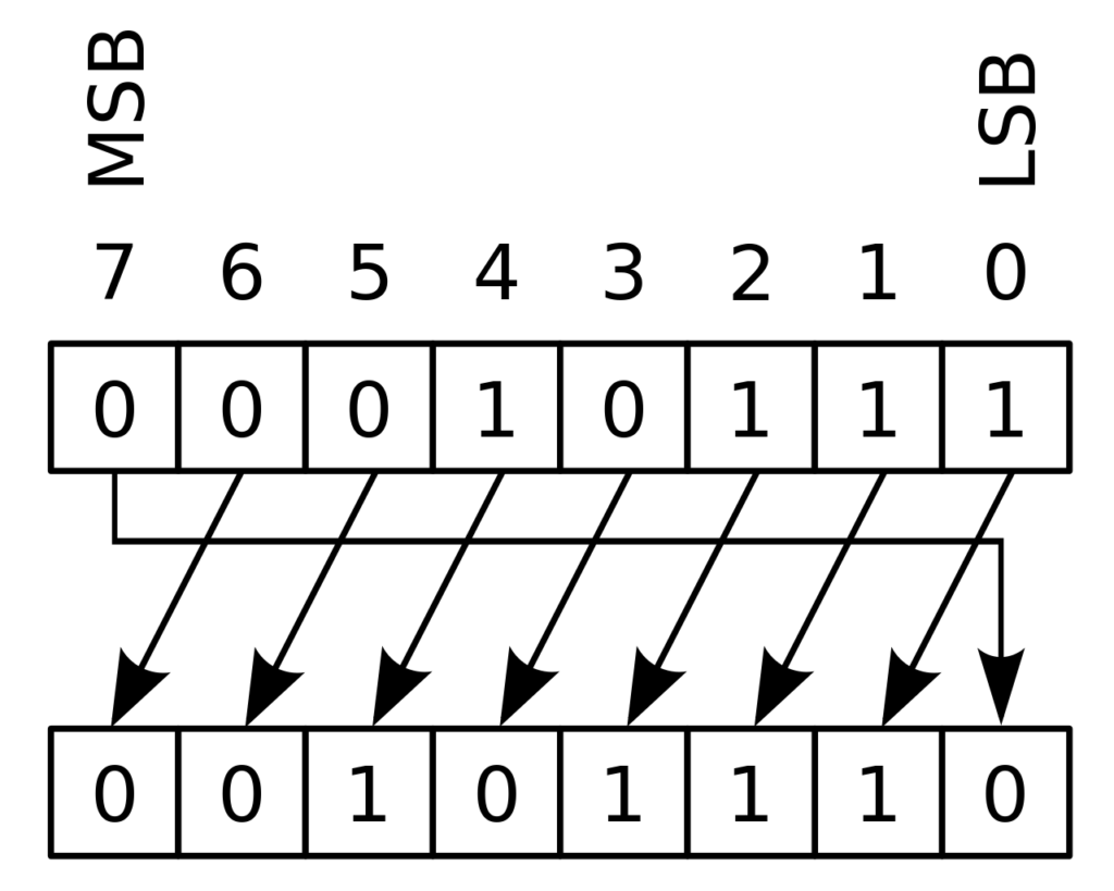
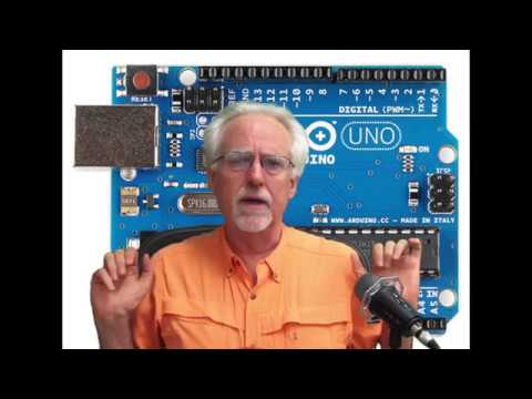
The Circular Shift Left function is illustrated below:
Illustration of Circular Shift Left Binary Function on an 8 bit number.
You can see that all bits shift to the left, with the Most Significant Bit, or MSB looping back to the Least Significant Bit, or LSB position.
Similarly, the Circular Shift Right Function is as follows:
This diagram illustrates the binary Circular Shift Right Function
There is actually a very easy way to implement this in a program. We illustrate it with an arduino program. Lets first consider the CSL function. We will first consider how to move the MSB to the LSB position. Remember from our earlier lessons, that dividing a binary number by 2 moves the bits to the right. We want to move the MSB 7 positions to the right, so we would divide by 27, which is 128. So, if we have a binary number myByte, we could move the MSB to the LSB by the equation:
myByte=myByte/128
With this we do the hardest part, which is to get the MSB to the LSB. Now we need to get the rest of the bits back, and in the left shifted position, we do that by multiplying by two. By combining these two functions, we end up with the solution of CSL being:
myByte=myByte/128+myByte*2
This simple equation will perform the CSL operation, when myByte is a Hexadecimal or Binary number (Byte type in Arduino).
We show the code below to implement the CSL an arduino with a 74HC595 chip:
Arduino
1
2
3
4
5
6
7
8
9
10
11
12
13
14
15
16
17
18
19
20
21
22
23
24
25
intlatchPin=11;
intclockPin=9;
intdataPin=12;
intdt=1000;
bytemyByte=0b11111110;
voidsetup(){
// put your setup code here, to run once:
Serial.begin(9600);
pinMode(latchPin,OUTPUT);
pinMode(dataPin,OUTPUT);
pinMode(clockPin,OUTPUT);
}
voidloop(){
// put your main code here, to run repeatedly:
digitalWrite(latchPin,LOW);
shiftOut(dataPin,clockPin,LSBFIRST,myByte);
digitalWrite(latchPin,HIGH);
Serial.println(myByte,BIN);
delay(dt);
myByte=myByte/128+myByte*2;
}
Similarly, the CSR binary function can be achieved with the equation:
In this lesson, we explore how to perform Logical Shift Left (LSL), and Logical Shift Right (LSR) functions on binary numbers, and we implement a circuit to perform these functions using an Arduino and a 74HC595 chip. We will demonstrate these functions on 8 bit binary numbers.
We start with the basic circuit and code which were developed in Lesson 42. In this lesson we are using parts from the Elegoo Arduino kit, which you can get HERE. We start with this circuit, which was explained in Lesson 42.
This is the schematic we use in this example to control 8 LEDs from the 74HC595 chip.
You can see that with this circuit, an 8 bit binary number can be visually displayed by illuminating the circuit LED. The goal of this lesson is to write code to perform LSL and LSR functions. The graphics below show conceptually how simple these functions are:
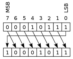
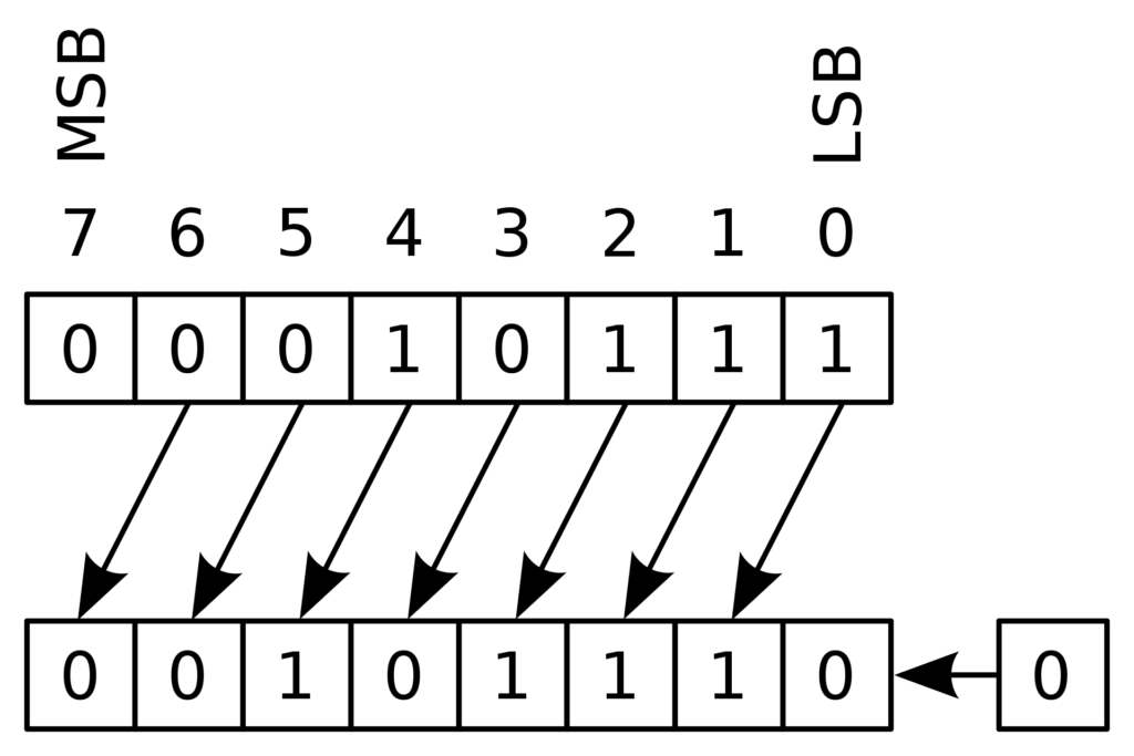
This diagram shows the Logical Shift Left function on an 8 bit binary number
MSB stands for “Most Significant Bit” and LSB stands for “Least Significant Bit”. You can see that the LSL function just moves each bit one to the left, and fills the empty LSB with a “0”.
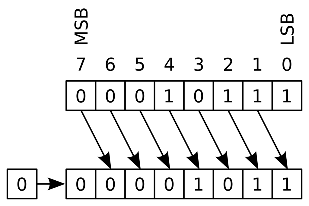
The LSR funtion is just as simple as illustrated below.
This diagram shows an 8 bit binary number undergoing a Logical Shift Right (LSR) funtion
Such shifts are often required when doing digital logic, so it is important to understand what the terms mean.
We can see that the LSL function can be performed by simply multiplying the binary number by 2. Similarly the LSR function can be performed by dividing the binary number by 2.
Code for LSL:
Arduino
1
2
3
4
5
6
7
8
9
10
11
12
13
14
15
16
17
18
19
20
21
22
23
24
25
intlatchPin=11;
intclockPin=9;
intdataPin=12;
intdt=1000;
bytemyByte=0b10000000;//Put your binary number here
In this Lesson we begin to work on developing a tilt stabilized platform using the BNO055 9-axis sensor, and we will take advantage of all the learning that happened in the first 22 lessons. Now though, we will be moving out of the virtual world of Vpython, and will begin working in the real world. In this lesson we focus on getting the gear together. You can go ahead and order your gear, and then next week we will begin assembling and coding. In addition to the arduino nano, and the BNO055, you will need:
NOTE: I am no longer recommending the MG995 four pack of servos, as I have recently gotten several bad batches, so have moved to the HiTEC linked above.