This Circuit Gives Visual Indicator if Board Has Been Tilted
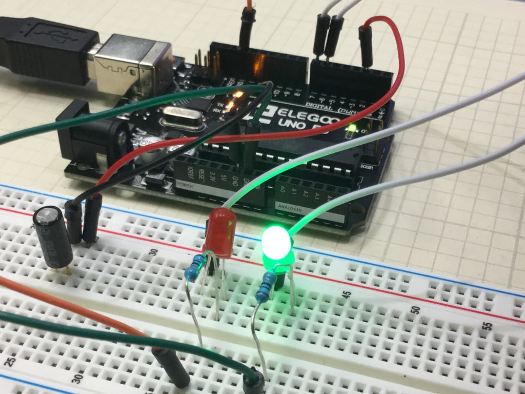
This is a simple project that allows you to create a circuit which will give a visual indication if the breadboard has been tilted. In the upright position, the Green LED is illuminated. To the left of the board is a tilt switch. If the project is tilted, the switch will go from the closed to the open condition. This can be detected on the arduino, and then the red LED is illuminated. The video below explains how to do this simple project.
You can get the kit we are using in these lessons HERE. You should create your own code based on the instructions in the video, but if you are having trouble, I include the code developed in the video below:
In this lesson we show you how to install Visual Python (Vpython) and show you how to begin to build 3D visuals. We introduce you to some of the basic objects and how how control how they look and where they are.
In this lesson we give you several examples of how to connect and program a stepper motor. Stepper motors are useful because they can produce very large torque at low RPM and are capable of extremely precise positioning. They are somewhat tricky to use, and you must be careful to not try and power them from an Arduino. Arduino can control stepper motors, but they must be powered from an external power supply.
If you want to follow along at home, you can order the Arduino Kit we are using HERE.
This is the code that allows you to toggle the direction of the stepper motor by pressing a pushbutton. The video shows all the details and how to connect the motor up.
In this lesson we show how to pass data from Arduino to Python using a Com Port. This is important for our 9-Axis IMU project as we want to take advantage of the processing power and 3D graphics capabilities of Python. Our goal is to get the date from Arduino to Python, and then create a dynamic 3D visualization of our system. The first step in this goal is to pass the data from arduino to Python.
In order to do this, a first step is to install the pyserial library. If you followed our python installation tutorial in lesson 11, then it is easy to install pyserial by just opening a windows command prompt, and then typing:
pip install pyserial
If this does not work, likely you did not install python according to the instruction in lesson 11.
In order to show a simple demonstration of passing data, we can use the following code on the arduino side, which just generates x, y, and z numbers and passes them to Python.
Arduino
1
2
3
4
5
6
7
8
9
10
11
12
13
14
15
16
17
18
19
20
21
22
23
intx=0;
inty=0;
intz=0;
voidsetup(){
// put your setup code here, to run once:
Serial.begin(115200);
}
voidloop(){
// put your main code here, to run repeatedly:
x=x+1;
y=y+2;
z=z+4;
Serial.print(x);
Serial.print(",");
Serial.print(y);
Serial.print(",");
Serial.println(z);
delay(100);
}
We can grab these numbers from the Com port on the Python side with the following code. Note that you should use the com port your arduino is on, which likely will not be the same as mine (which was ‘com5’).
Python
1
2
3
4
5
6
7
8
9
10
11
12
13
14
15
16
importtime
importserial
arduinoData=serial.Serial('com5',115200)
time.sleep(1)
while(True):
while(arduinoData.inWaiting()==0):
pass
dataPacket=arduinoData.readline()#reply
dataPacket=str(dataPacket,'utf-8')
print(dataPacket)
splitPacket=dataPacket.split(",")
print(splitPacket)
X=float(splitPacket[0])
Y=float(splitPacket[1])
Z=float(splitPacket[2])
print("X=",X," Y=",Y," Z=",Z)
The above example is just a simple method for passing different channels from Arduino to Python.
For our IMU project, we want to use the code we left off with Lesson 10. However, note we can scale back on the number of data channels, because we just want the calibration data and then the final roll, pitch and yaw numbers. This is the arduino code that will pass those parameters.
In this lesson we show you a quick hack that will allow you to incorporate a pushbutton switch into an Arduino project without having to use an external pullup resistor, and still get very stable operation. The trick is to create a digital input pin, which in our example is pin 2. We then digitalWrite that INPUT pin HIGH. What that does is put an internal pullup resistor on pin 2, and then connects it to 5 volts. In effect, we are using a clever command to use the Arduino’s internal pullup resistors. The code below is what we used in the video. Enjoy!
Arduino
1
2
3
4
5
6
7
8
9
10
11
12
13
14
15
16
intbuttonPin=2;
intbuttonValue;
intdt=100;
voidsetup(){
// put your setup code here, to run once:
pinMode(buttonPin,INPUT);
digitalWrite(buttonPin,HIGH);
Serial.begin(9600);
}
voidloop(){
buttonValue=digitalRead(buttonPin);
Serial.print("Your Button is: ");
Serial.println(buttonValue);
delay(dt);
}
Making The World a Better Place One High Tech Project at a Time. Enjoy!