
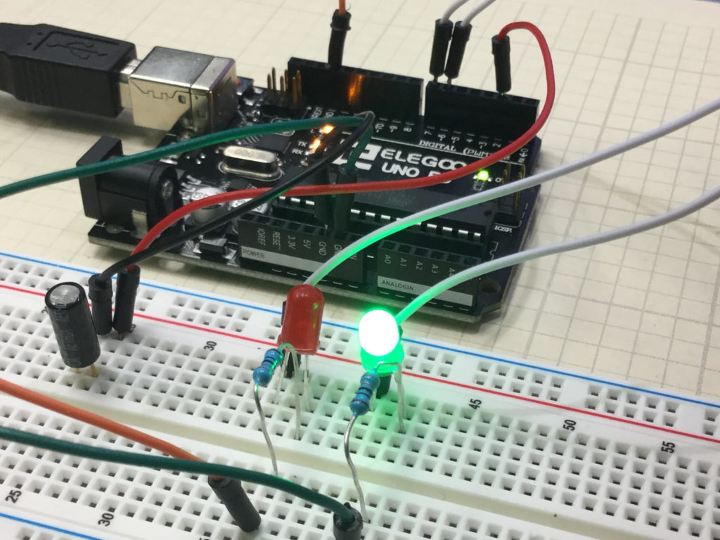
This is a simple project that allows you to create a circuit which will give a visual indication if the breadboard has been tilted. In the upright position, the Green LED is illuminated. To the left of the board is a tilt switch. If the project is tilted, the switch will go from the closed to the open condition. This can be detected on the arduino, and then the red LED is illuminated. The video below explains how to do this simple project.
An official Arduino Uno R3 is available HERE. In this new series of lessons, I will be using the sensor and other components found in this KIT.
You should create your own code based on the instructions in the video, but if you are having trouble, I include the code developed in the video below:
|
1 2 3 4 5 6 7 8 9 10 11 12 13 14 15 16 17 18 19 20 21 22 23 24 25 26 27 28 |
int tiltPin=2; int tiltVal; int redPin=7; int greenPin=6; void setup() { // put your setup code here, to run once: pinMode(tiltPin,INPUT); pinMode(redPin,OUTPUT); pinMode(greenPin,OUTPUT); digitalWrite(tiltPin,HIGH); Serial.begin(9600); } void loop() { // put your main code here, to run repeatedly: tiltVal=digitalRead(tiltPin); Serial.println(tiltVal); if (tiltVal==0){ digitalWrite(greenPin,HIGH); digitalWrite(redPin,LOW); } if (tiltVal==1){ digitalWrite(greenPin,LOW); digitalWrite(redPin,HIGH); } } |