The cool thing about the arduino is you can program it to interact with the real world. The arduino can connect to and interact with a variety of sensors and actuators which allow you to monitor what is happening around you, and to control things like motors, relays, and servos. To do this though, you need to be able to connect components to the arduino. For prototyping, that is most easily done by using a breadboard. If you want to play along at home, and follow all these lessons with the same components I am using, you can order this Arduino kit.
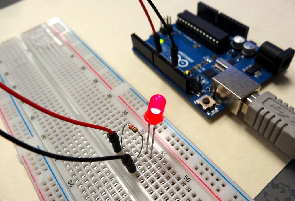
The video below describes in detail how to use a breadboard, and even helps you get your first circuit prototype up and running.
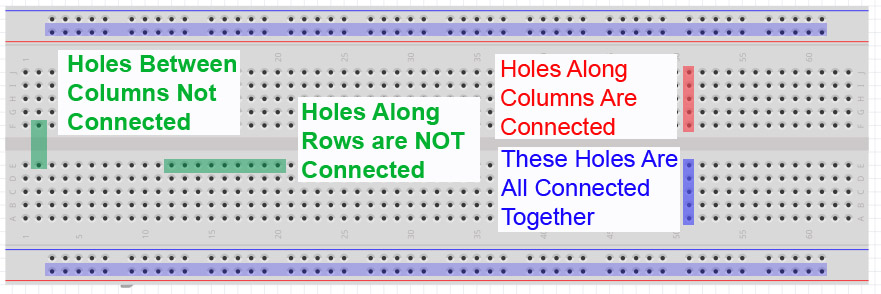
As explained in the video, key to using the breadboard to create circuits is to understand how the little holes on the breadboard are connected. This graphic will help you understand which holes are connected and which are not.
Breadboard for prototyping your Arduino Circuits
Study this graphic, and make sure you understand how the breadboard works. You can see that to connect two leads together, they should be plugged into the same column on the breadboard. It does not matter which column, as long as the two leads are in the same column.
It will take some practice, but if you follow the video carefully, you should be able to get your first circuit connected and working.
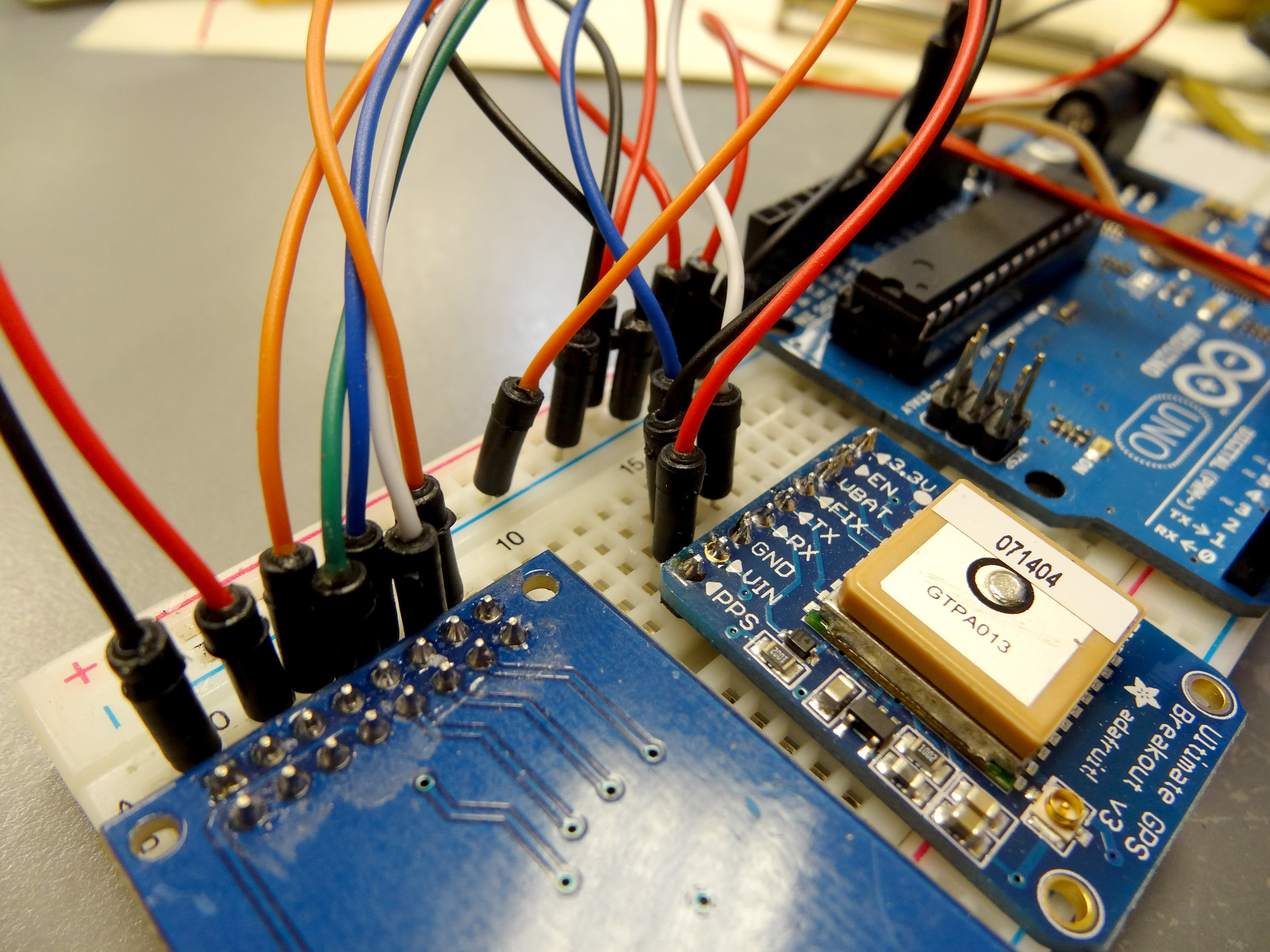
The neat thing about using breadboards and jumper wires to build a circuit is that it is a quick and easy way to get your prototype up and working. It is an excellent way to get your circuit and code debugged. The wires are very easy to connect by just plugging them into the holes. the downside is, those wires come out just as easily as they went in.
Breadboard Prototype Wires are Not Securely Connected
The breadboard prototype is great for getting your prototype going, but to use in a real project like a robot, unmanned aerial drone, or high altitude balloon, you will need a more secure way to connect your circuit up. Typically the next step for commercial products would be to order a custom PC board, and then solder the components into the board. This is a great way to go, but there are some pretty large barriers to doing this. There is a fairly steep learning curve to the board design software. The second issue is that even for simple projects the minimum order is usually around $100. Once you order the board you really can not tweak or make changes to your design. Also, you typically solder the components into the board, so you can not take it apart and use your components in other projects.
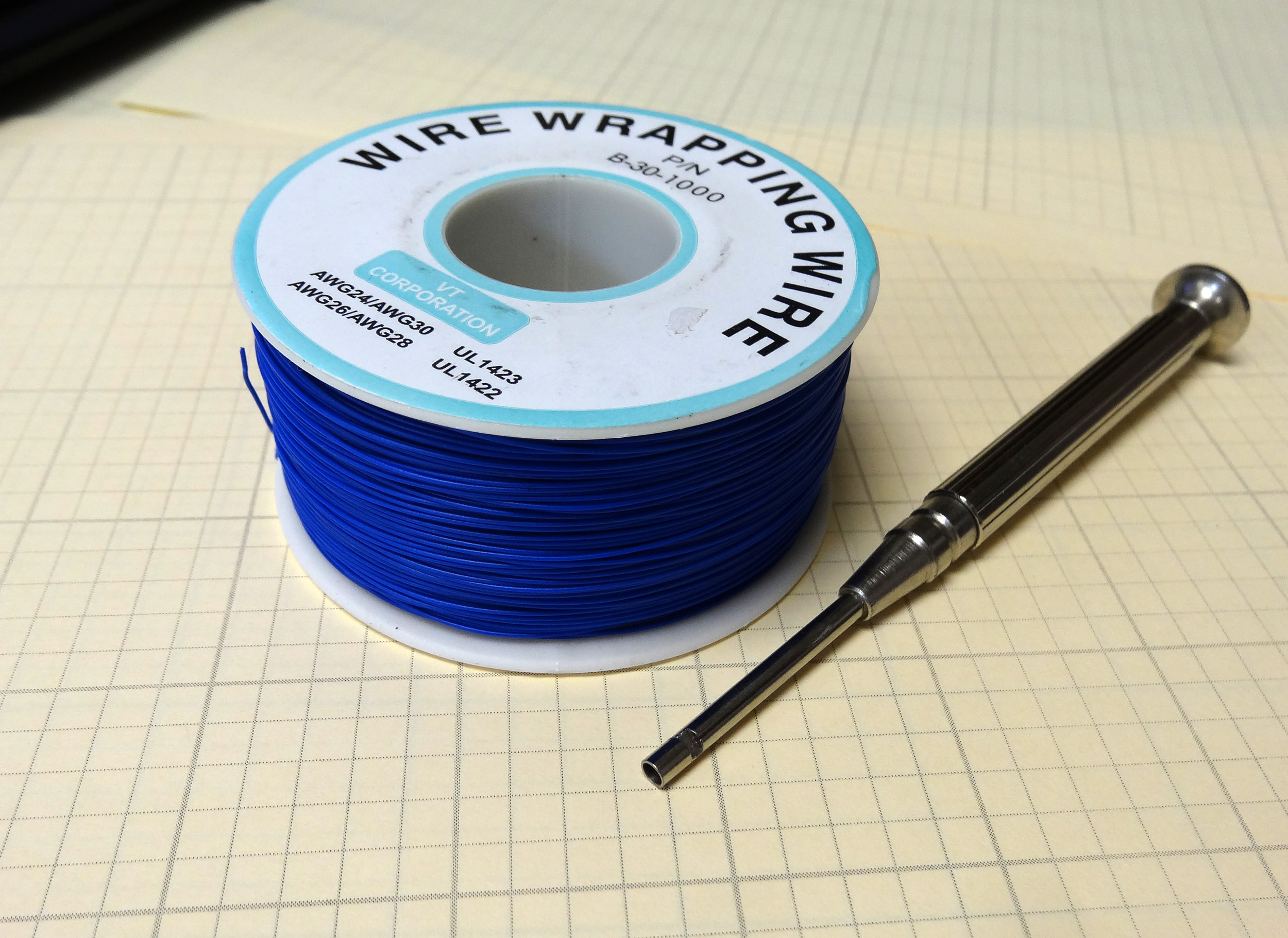
Wire Wrapping Tool and Wire
Luckily, there is a good options for students working with a limited budget. It is an almost lost art form known as Wire Wrapping. To make a robust circuit suitable for deployment in real projects, you need a minimum of equipment, and it is very easy to learn.
Once you have your gear, the rest is pretty simple. Measure out the length of wire you need, leaving excess on each end for the “wrap”. I like to use about 1 inc of wire for a wrap. Hence, I would leave 1 inch extra on each end, or two inches total extra for each wire. Then strip about 1 inch of wire off each end. Insert the wire into the small hole or indention in the wire wrap tool. Place the tool over the post or pin you want to wire wrap, and gently rotate the tool clockwise until the wire is wrapped around the post. Simple as that. The video above shows you just how to use it.
Making The World a Better Place One High Tech Project at a Time. Enjoy!