Tag Archives: Arduino

Python with Arduino LESSON 5: Finishing our Virtual Reality Example

This Lesson finishes the work that was begun in Python with Arduino LESSON 4. In that lesson we built the circuit and programmed the arduino to measure the distance to a target and the color of the target. The program then output that data to the serial port. In today’s lesson we will use python to read that data stream, and use the data to dynamically update a virtual world we create.

You will need to start with the work in LESSON 4 to get your circuit working, and your arduino programmed up. Once you have done that, you are ready to use Python to program up your virtual world. Remember you will need to have the pyserial and the vPython libraries loaded. We showed how to install the software in Python with Arduino LESSON 2.

In the video we will go through the process step-by-step to create a virtual world. The code we end up with is posted below. You should not copy and paste the code, but just glance at it if you get stuck. In the end, you should develop your own virtual world and just use mine as a guide if you need more help.

 The video explains each line of the code.  Play around and tweak the values and see the effect on your virtual scene. Now your assignment is to take what you have learned here, and continue to expand your virtual world. Add objects to your virtual scene. Perhaps build an object for the breadboard, color sensor and arduino. I will give you several days to do this, and then when I come around for a project grade, I will want to see who has built the most impressive virtual scene. You should go well beyond the simple demonstration I have done here.

Python with Arduino LESSON 4: Expanding your Virtual World

In this lesson we will expand the virtual world we created in Python with Arduino LESSON 3. We will be creating a virtual world that will track a simple scene in the real world. In this project, the virtual world will track both the position and the color of a target in the real world. This lesson requires that you have the Python software and libraries installed, which we explained in LESSON 2.

This is our circuit with the HC-SR04 ultrasonic sensor and the TCS230 Color Sensor

This Lesson will be a bit more involved, and I will take you through it step-by-step. I will need to break things into two parts. In today’s lesson we will cover the Arduino side. We will develop the software that will measure distance and color, and then send those numbers over the serial port. Then in tomorrows lesson, we will develop the Python software to create a really cool virtual graphic to display the data in a virtual world.

For this project you will need the HC-SR04 ultrasonic sensor, the TCS230 Color Sensor, the Arduino Microcontroller, and some male/female jumper wires to connect to the color sensor.

The Ultrasonic Sensor can be attached per the schematic below:

Simple Circuit for Measuring Distance

Detailed tutorial on using this sensor was described in Arduino LESSON 18, so we will not go through all the details of using the sensor here. Review that lesson if you need more help. Key point here is to connect it as seen in diagram above.

You will also need to connect up the Color Sensor.

Connecting the Color Sensor to the Arduino

Color Sensor Pin
Arduino Pin
S0 GND
S1 5V
S2 pin 7
S3 pin 8
OUT pin 4
VCC 5V
GND GND

Use of the color sensor was described in detail in Arduino LESSON 15.  You should be able to develop to write the software yourself based on earlier lessons to make measurements from both the Color Sensor, and Ultrasonic Sensor, but if you get stuck, you can glance at my code below. Again, it is important for you to write your own code and not copy and paste mine. Mine is just a reference if you get stuck.

The key point to notice with this code is the print statements, summarized below:

 Notice that we are printing  our color strengths and distance on one line separated by commas. It is important to note the order of the data. When we read this in Python, we will read it in as one line of text, and then we will parse it into its individual values. So, we must make note and remember the order the data is arranged in in this line.

Remember when you have your python program reading this data, you must have your serial monitor closed. For now though, run your program and look at the serial monitor to verify you are getting correct data in the expected format.

In the next Lesson, LESSON 5, we will build the Python program to create a virtual world from this data.

Python with Arduino LESSON 2: Installing the Software

There are some really incredible things we can do when we get our little Arduino to talk to the big bad Python programming language. To do that, we have to start by downloading some software. Never fear . . . it is all free and I will take you step by step through the installation. The video above shows you how to do it. If you are the impatient and technically adept type, you can download these three software packages:

1) Download and Install Python 2.7.8. Please note all my tutorials use this flavor of python. If you want to follow my tutorials, do not download a Python 3.x. Also download 32 bit version of the software, even if you have a 64 bit windows machine.

2) Download and Install Pyserial version 2.7. Again, download the 32 bit version of the software.

3) Download and install the Vpython library for 32 bit windows.

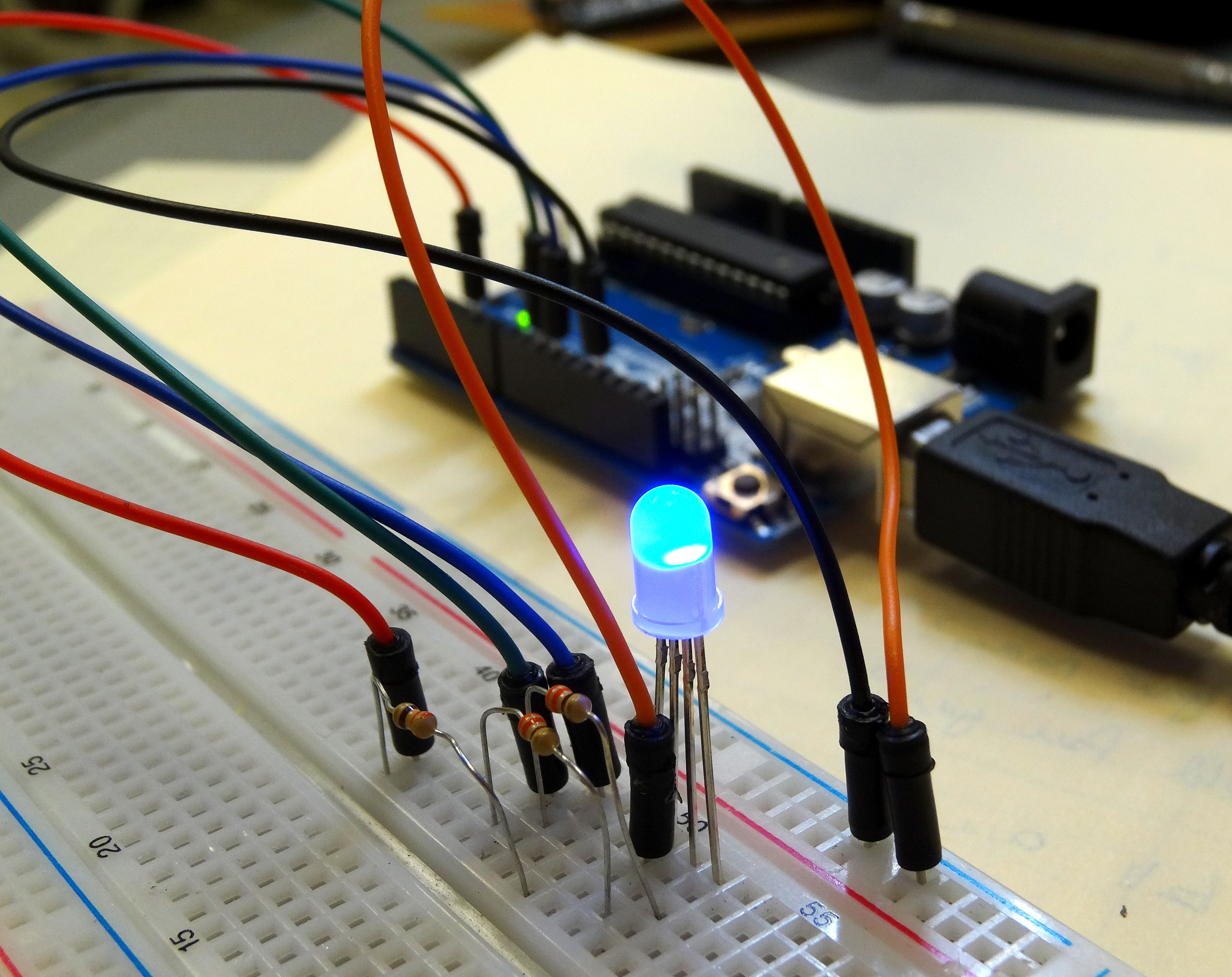
Now, lets get python and arduino talking together. First up, we need a simple program to get the Arduino sending data over the serial port. The following program is a simple program that will have the Arduino count and send the data to the serial port.

Now, open the VIDLE environment which you downloaded with the Vpython library. Once you have done that, you are ready to write a Python Program that will go out and read the data over the serial port. Full explanation is in the video. Do note, however, that the line:

This is for a windows machine. Also, the ‘com11’ has to be adjusted and set to whatever com port your arduino is talking on. You can figure that out by looking at Tools – Port on the Arduino. Set this parameter to whatever port your Arduino is talking on. Then, the baud rate needs to match as well. You can use whatever you want by Arduino and Python need to be on the same baud rate, which you set on this line of code. OK, the complete Python code to read the Arduino data from the serial port is here:

Simple as that! Welcome to the world of having the Power of Python now at your fingertips.

LESSON 13: Controlling RGB LED with Arduino

OK, we are ready to move forward and learn new circuit skills and new programming skills. In today’s lesson we will learn how to control an RGB (Red, Green, Blue) LED with an arduino microcontroller! This will introduce us to a new circuit component, and will require us to learn some new programming skills.

Circuit to control RGB LED with an Arduino

An RGB LED is basically three LED’s in one. It has 4 leads. One lead, the long lead, is the common ground. Then one lead controls the red LED, one lead controls the green LED, and one lead controls the blue LED. All three of the LED’s are connected to ground through the same pin. You can control the color you get out of the LED based on the voltages you write to the different control pins. A schematic will probably help you understand how the component works and how you should hook up to it.

This schematic shows how to work with a common cathode RGB LED

This picture shows the four pins for a common cathode RGB LED. “Common Cathode” just means that the LED’s share the ground pin. There are also “Common Anode” LED’s which share a common high voltage pin, and then each color has its own ground. I think these are much more confusing, but just mention them so that you know that this tutorial is for the common cathode type.  The Sparkfun Inventor Kit has the common cathode configuration, which is the type I prefer. Also note in the drawing you can see that the length of the pins is your clue as to which pin controls red, which green and which blue.

Now lets think about using this in a circuit. As you can see in the schematic, all three of the LED’s share a common ground pin. You can easily see that pin should be connected to your circuit ground. Now, think about how you would connect the control pins. To control a normal LED, you needed to connect to one arduino output pin. To control this LED, how many control pins will you need to use on the arduino? That’s right . . . you will need three control pins. Also, remember than you never connect an LED directly to a voltage source, you always use a series current limiting resistor (typically 330 ohms). For these new RGB LED’s how many current limiting resistors will we need? We will need three . . . each color control pin will need its own current limiting resistor. So each color control pin will connect to an arduino output pin through its own current limiting resistor. Once that is hooked up, we can control what color the LED is by writing voltages from the arduino to specific legs of the RGB LED. If we write a voltage to the red pin, the LED will be red. If we write a voltage to the blue pin, the LED will be blue. Also the exciting thing is that if you write voltages to multiple pins, you can get the in between blended colors. Basically by analogWrite-ing different values to the 3 different control pins, you can get any imaginable color. But first, lets go ahead and get our circuit set up. The following schematic controls red from arduino pin 6, green from arduino pin 10 and blue from arduino pin 11. Go ahead and hook this circuit up.

Arduino circuit to control the color of an RGB LED.

Now lets play around with a program that will independently turn on the different colors. We will start simple so we can get an intuitive feel for how the LED works.

 With the code above, what color do you anticipate the LED will be? Hook up the circuit and type in the code, and see what happens. It is important that you type in the code. Do not cut and paste my code. You need to type it in. When you type it in, you will probably make mistakes and when you do you will have to troubleshoot or debug your code. That means you have to find your mistakes. All programmers make mistakes, and it is important very early on to learn how to find your mistakes.

Modify the code above so that the LED turns green.

Now modify it again so that the LED turns red.

Now try for the in between colors. How would you get the LED to turn orange? Play around with achieving different colors. Try to get the following colors:

Cyan

Magenta

Yellow

Orange

Purple