In this lesson, we explore how to perform Logical Shift Left (LSL), and Logical Shift Right (LSR) functions on binary numbers, and we implement a circuit to perform these functions using an Arduino and a 74HC595 chip. We will demonstrate these functions on 8 bit binary numbers.
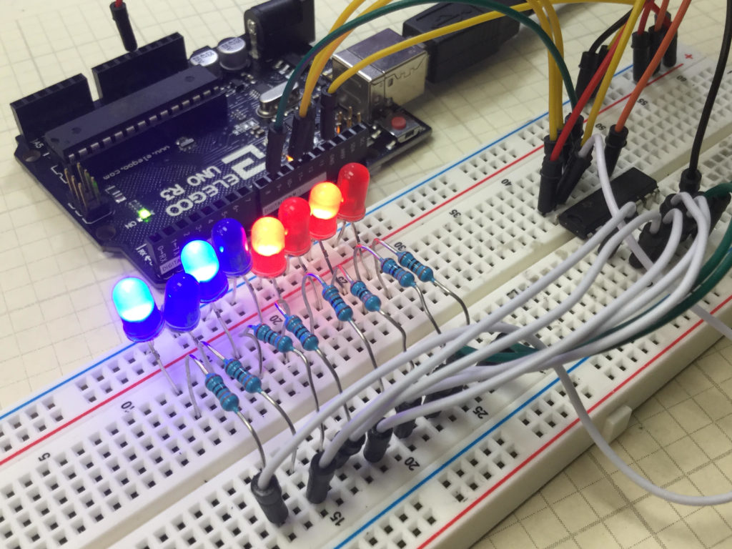
We start with the basic circuit and code which were developed in Lesson 42. In this lesson we are using parts from the Elegoo Arduino kit, which you can get HERE. We start with this circuit, which was explained in Lesson 42.

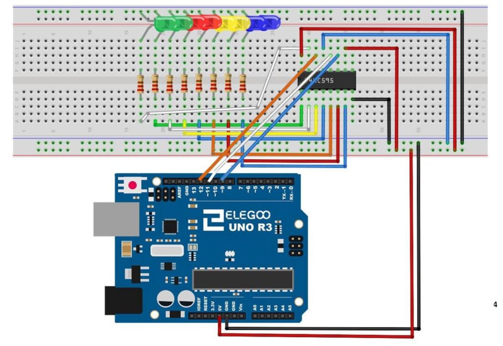
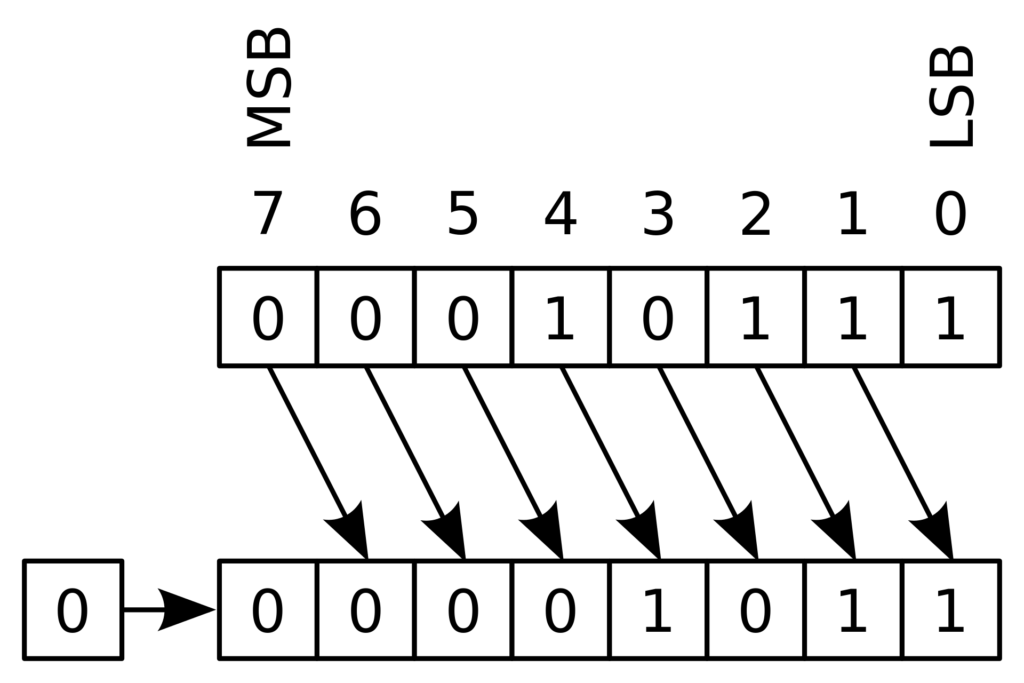
You can see that with this circuit, an 8 bit binary number can be visually displayed by illuminating the circuit LED. The goal of this lesson is to write code to perform LSL and LSR functions. The graphics below show conceptually how simple these functions are:

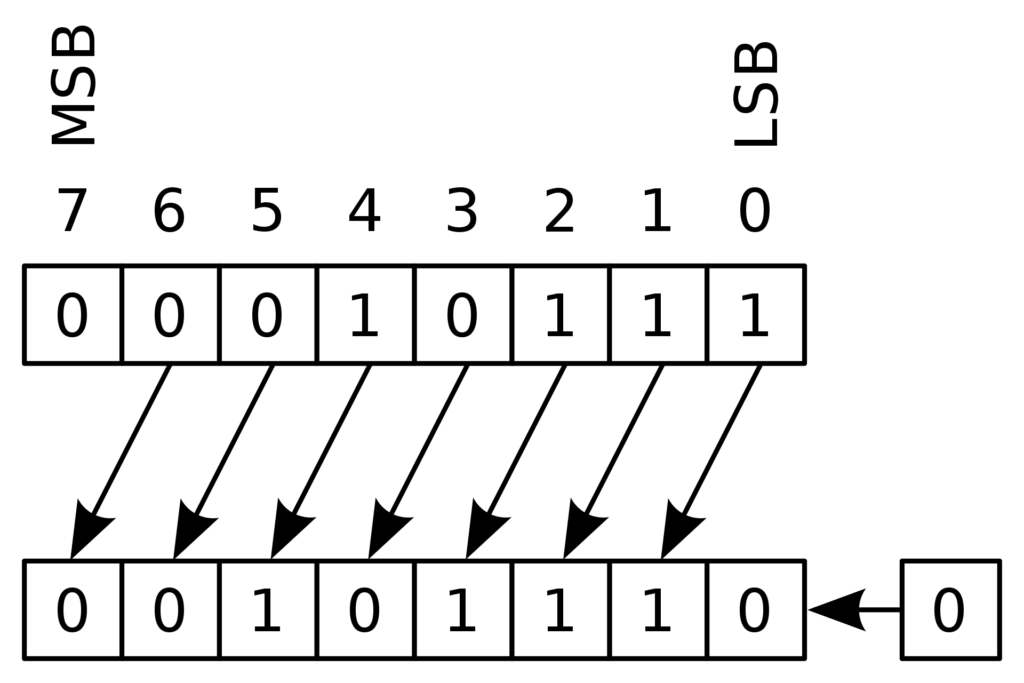
MSB stands for “Most Significant Bit” and LSB stands for “Least Significant Bit”. You can see that the LSL function just moves each bit one to the left, and fills the empty LSB with a “0”.
The LSR funtion is just as simple as illustrated below.
Such shifts are often required when doing digital logic, so it is important to understand what the terms mean.
We can see that the LSL function can be performed by simply multiplying the binary number by 2. Similarly the LSR function can be performed by dividing the binary number by 2.
Code for LSL:
|
1 2 3 4 5 6 7 8 9 10 11 12 13 14 15 16 17 18 19 20 21 22 23 24 25 |
int latchPin=11; int clockPin=9; int dataPin=12; int dt=1000; byte myByte=0b10000000; //Put your binary number here void setup() { // put your setup code here, to run once: Serial.begin(9600); pinMode(latchPin,OUTPUT); pinMode(dataPin,OUTPUT); pinMode(clockPin,OUTPUT); } void loop() { // put your main code here, to run repeatedly: digitalWrite(latchPin,LOW); shiftOut(dataPin,clockPin,LSBFIRST,myByte); digitalWrite(latchPin,HIGH); Serial.println(myByte,BIN); delay(dt); myByte=myByte*2; } |
Code for LSR function:
|
1 2 3 4 5 6 7 8 9 10 11 12 13 14 15 16 17 18 19 20 21 22 23 24 25 |
int latchPin=11; int clockPin=9; int dataPin=12; int dt=1000; byte myByte=0b10000000; void setup() { // put your setup code here, to run once: Serial.begin(9600); pinMode(latchPin,OUTPUT); pinMode(dataPin,OUTPUT); pinMode(clockPin,OUTPUT); } void loop() { // put your main code here, to run repeatedly: digitalWrite(latchPin,LOW); shiftOut(dataPin,clockPin,LSBFIRST,myByte); digitalWrite(latchPin,HIGH); Serial.println(myByte,BIN); delay(dt); myByte=myByte/2; } |