Tag Archives: Potentiometers

LESSON 19: Arduino LCD Display

In this lesson we are going to learn to use an LCD display. This really allows us to take our Arduino projects to that next level! We will first get the LCD hooked up and show we can display a simple welcome message. Then we will use it to display the distance measurement being made from the ultrasonic sensor. So, do not take your project apart from LESSON 18.

This circuit displays the distance you measure on a cool LCD.

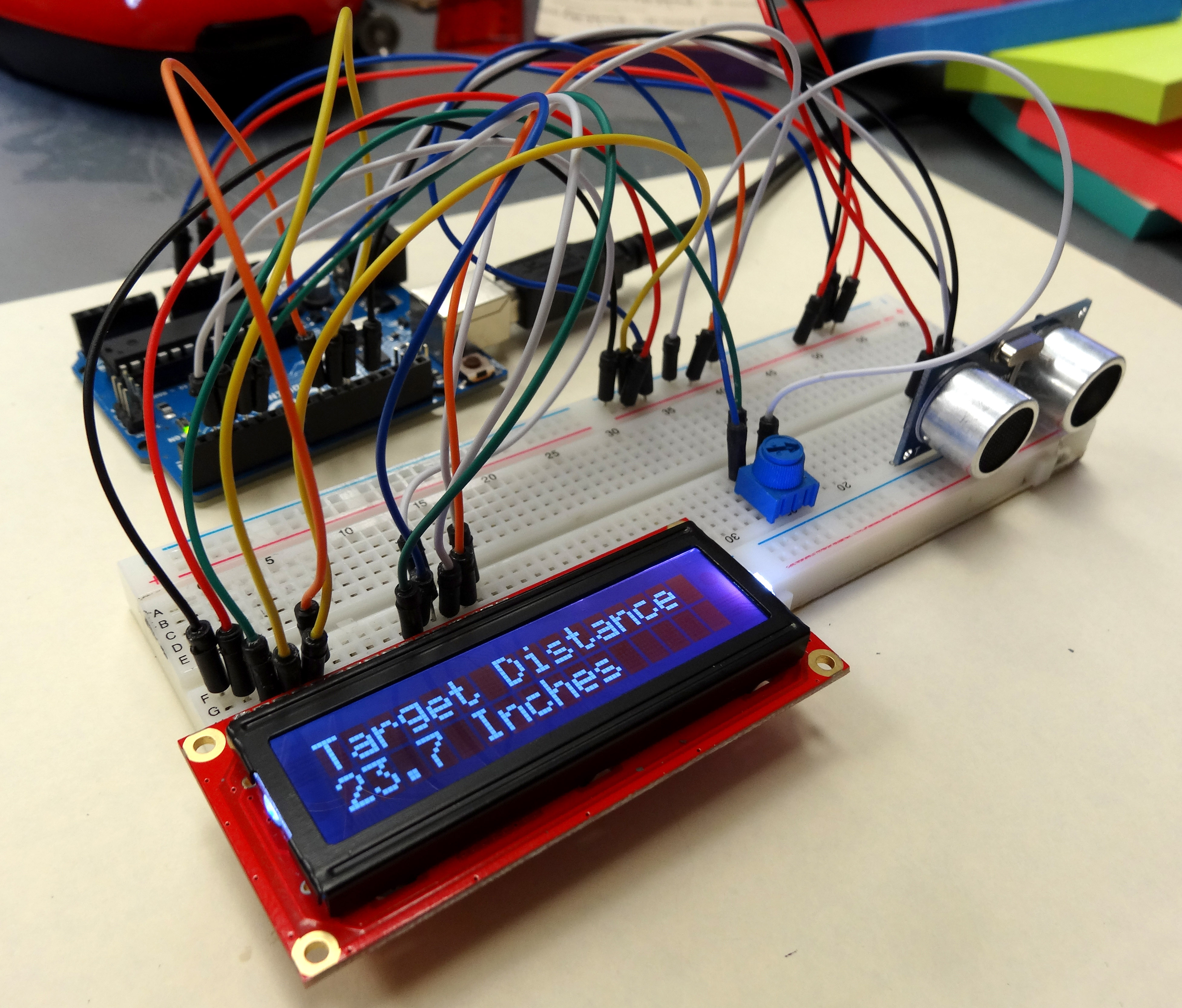
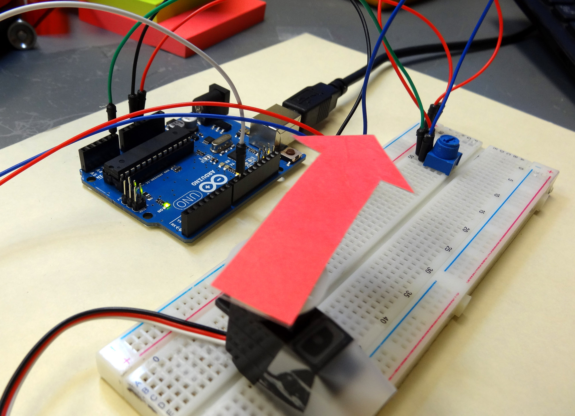
This table shows you how to connect your Sparkfun Inventor Kit LCD to your arduino. (If you do not have the kit, and want an LCD like the one in this tutorial you can order it HERE.) When oriented like the photograph above, pin one is the pin in the upper left corner, and they are numbered sequentially from left to right. The table below shows the connections needed to allow the arduino to work with this LCD using the code we will write in this lesson. The pinout of other LCD might be different, but if you connect the LCD named pins in column 2 to the Arduino pins in column 3 in the table below, you should be able to get many of the 16X2 LCD’s to work.

Connections for Sparkfun Inventor Kit LCD
(for others column 1 might be different)
LCD Pin # LCD PIN NAME Arduino Pin
1 VSS GND
2 VDD 5V
3 V0 Pot Center Pin
4 RS 10
5 RW GND
6 E 9
7 DB0 NOT CONNECTED
8 DB1 NOT CONNECTED
9 DB2 NOT CONNECTED
10 DB3 NOT CONNECTED
11 DB4 Pin 5
12 DB5 Pin 4
13 DB6 Pin 3
14 DB7 Pin 2
15 Backlight LED +V 5V
16 Backlight LED GND GND

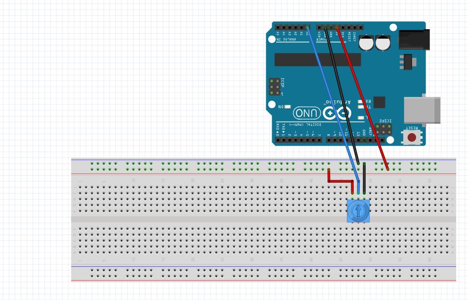
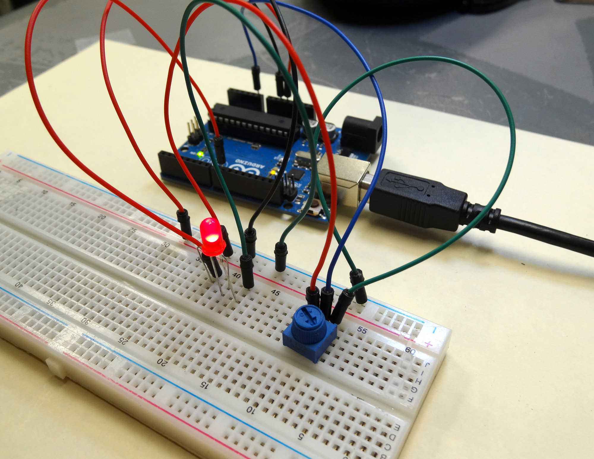
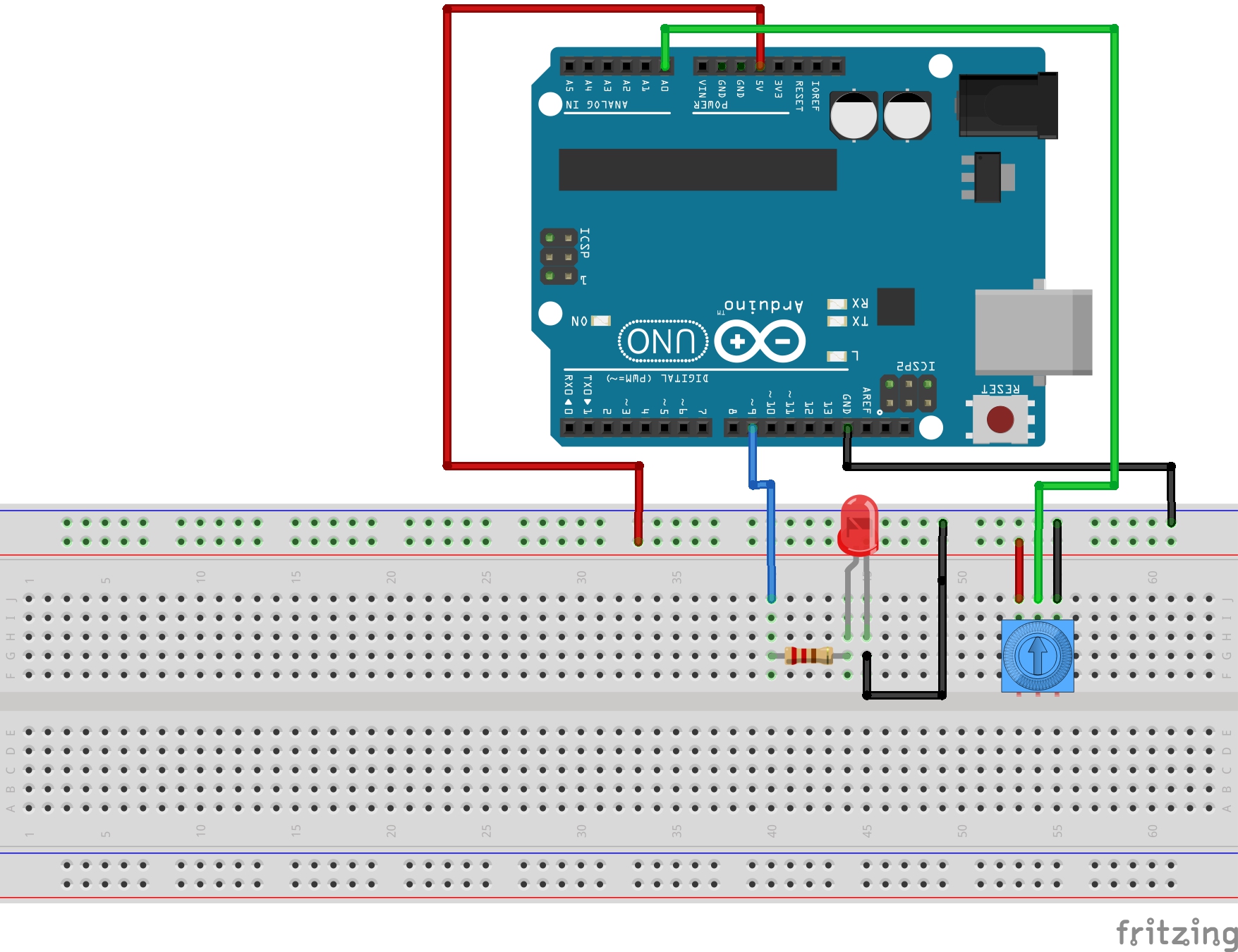
For this project, you can use the table above to connect your LCD to the Arduino.  The diagram below is a graphical representation of the connections for LCD like mine.


This diagram shows how to connect my LCD to the Arduino.

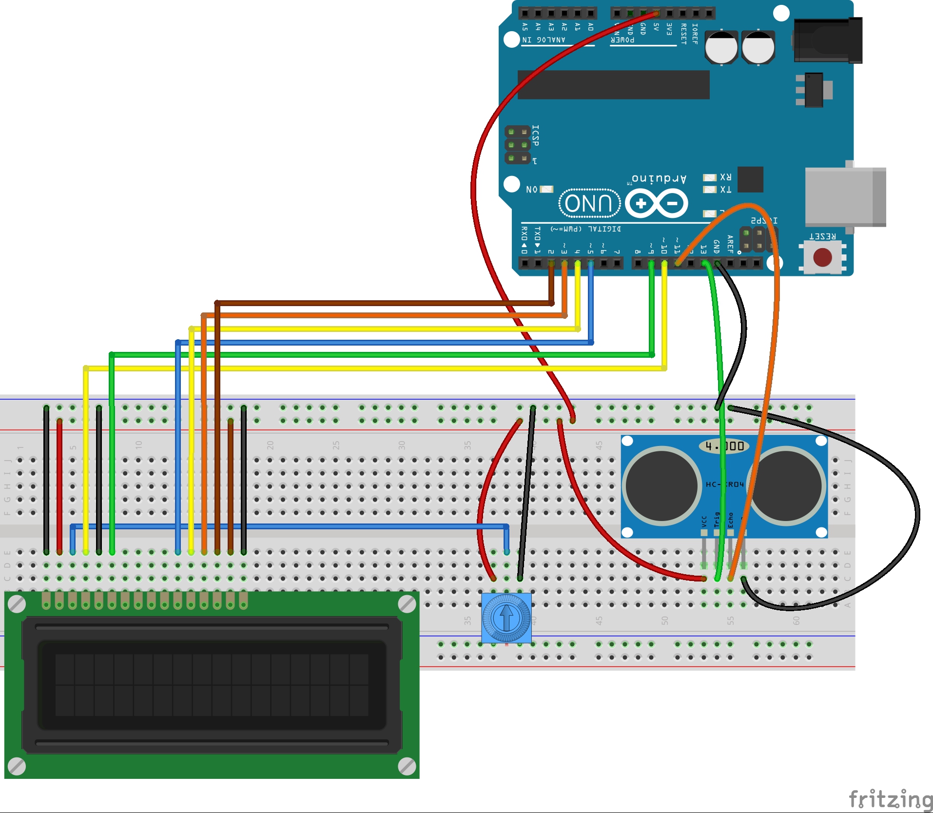
These LCD are tricky to hook up because there are so many wires. You have to be very careful,  and you have to make sure your LCD is oriented properly. Check the spec sheet that comes with you LCD carefully to verify connections are correct.

Once the LCD is wired up, it is fairly straightforward to use.

 At the top of your code, you will want to make sure that you load the LCD library. This is a standard library that comes with your arduino software.  You load the library by putting the following code at the top of your program:

Also at the top of the code, you want to create you LCD object, which also tells Arduino how you are connected to it:

The numbers tell Arduino that we have RS hooked to pin 10, E hooked to pin 9, DB4-DB7 connected to Arduino pins 5-2, as shown in the table above.

In the void setup, you will want to tell the Arduino that your LCD has 16 columns and 2 rows.  You should put this code in your void setup, since you only need to do it one time:

You are now just about ready to start sending messages to the LCD. You need to start by telling the Arduino where on the LCD to begin the message. Remember that it always wants column first, then row, and that it starts with ‘0’. Therefore, the upper left character would be column 0, row 0, or (0,0). To set the cursor to the upper left corner, you would send command:

So now lets make a simple Counter. We will count off seconds. We start by printing “My Timer” on the first row. We do that with the command:

Now we would go to the second row and print a counter. Lets bring all the code together in the following working program.

Run this program. If you have your LCD hooked up correctly, you should see the counter working. If it is not showing, you probably have miswired the circuit. Go back and check your circuit carefully. You also might need to play with the setting on the potentiometer to get the contrast set correctly.

Now, watch the counter count up and down carefully. You should notice something peculiar as the counter counts backwards. What do you see that is not good? What you should see is that as you count down from 10 to 9, you end up with an extra ‘s’ on the word ‘Seconds’. You end up with ‘Secondss’. This is a vexing problem which occurs just about every time you try and use an LCD. The reason is that when you go from 10 to 9,  printing the number goes from needing two digits to one digit. Then, when you print ‘Seconds’ it is shifted to the left by one character, and you are still left with the last ‘s’ from the previous time you printed ‘Seconds’. Hence you are left with a mess.

There are two ways to clear this up. One way would be to specifically set the cursor to a correct position before printing ‘Seconds’. This would put it in the same place every time, and alleviate the problem. The other possibility is to print a blank line each time through the loop to clear the second line of the LCD. This is something you need to play around with and understand, because it seems to come up every time I try and use an LCD. Look at this code, and try it, and make sure you understand why it fixes the problem.

OK, your assignment is to play around with the LCD and become comfortable with it. Show me that you can make it do some new and interesting things. Write a program of your choosing that uses the LCD as a display. You might consider making it the display for one of the projects you did in one of our earlier lessons.


LESSON 16: Controlling a Servo with Arduino

Its time to get moving! In this project we show you how to get things moving with Arduino. You will need an arduino, a servo, a potentiometer and some wires. If you have the sparkfun inventor kit, it has everything you need (You can pick up the inventor kit HERE).

Circuit for controlling a Servo from the Arduino using a Potentiometer

For this project, our objective is to control the position of a servo based on the setting of a potentiometer. The servo should “track” the position of the potentiometer. In order to do this, we will need to start with our Voltage Divider Potentiometer circuit from LESSON 10. In addition, we will need to hook the servo up. for the servo in the sparkfun kit, it has three wires . . . red, white, and black. The red line is for power, so it should be hooked up to 5V from the arduino. The black line is ground, and should be hooked up to ground on the arduino. The white line is the control line, and it should be hooked up to one of the arduino pins with a squiggly line.  For this example, I am using pin 9. The small servo that comes with the sparkfun kit can be powered directly from the arduino. Understand that many servos draw lots of power, and require a separate power supply, and just the control line connects to the arduino. Realize that you must be careful and not hook a larger servo to the arduino for power, as that can damage your arduino. The one in the sparkfun kit can be driven by the arduino without a problem.  Also, some servos have a different color code on the wires. Many have red/orange/brown wires. For many of these types, the red is for power, the orange is for the control line, and the brown is for ground. Be sure to check the instructions on your servo to verify the color code.  As a reminder, this is circuit diagram for the potentiometer, which you will be using in this project.

This simple circuit allows you to create a voltage divider with a potentiometer, which we will use to set position of the Servo.

Most servos are designed to be operational in a range from 0 degrees to 180 degrees. The truth is though, that most will not operate over that full range. Also, you need to know that overdriving the servo beyond the range it wants to be in can damage both your arduino and your servo. Each servo is different, and sometimes two servos with same model number from the same manufacturer will have different ranges. Especially in the cheap ones (like in the sparkfun kit) have very different ranges.

So before going to far in any project you need to determine the range that your particular servo will operate in. In order to do this we need to write a simple program that will move the servo. In order to control the servo from the arduino, there are several things that must be done. The first is that you must “load” a library. A library is a special set of code written by the folks who make or sell the device in order to make it easier for you to work with. Libraries allow us to work with components in a more intuitive way. For the servo, you need to load the servo library, which comes with the arduino software you originally downloaded. To load the library, you need the following code at the top of your program:

Then, you need to create a servo “object”. This object will then be something you interact with to make the servo move. You can all the object anything you want, but I think I will call mine “myPointer” since I am going to make my servo point at things. The code to create the servo object would then look like this:

OK, now to make the servo go to a certain position, I would just have to issue a command like this:

This command goes to ‘pos’ which should nominally be between 0 and 180.  But remember that most servos will not go over that full range, so we will need to play around to see what range our servo can safely achieve. Also, the short 15 millisecond delay after moving the servo gives it time to get there and settle down. Never try and write the servo faster than it can naturally move.

The one other thing you need to do is let the arduino know which pin the servo is connected to for the control line. We are using pin 9, and will set up a variable at the top of the code to set servoPin=9, but it can be any pin that can analogWrite (one with a squiggly line).  To tell your arduino where the servo is connected, for the case of my servo which I names myPointer, the following code should be put in the void setup:

What you need to do now is write a program that will input the user for a position, and then write that position to the servo. The purpose of this is to determine the natural range of your particular servo. You should write this program yourself, but if you get stuck you can look at my code below. You should use this as a help if you need it, but your should not cut and paste it. Write your own code!

OK, with this code we should see the arduino prompt the user to a position and then write that position to the servo. The thing to do with this code is play around and figure out what range of motion your arduino can achieve. If you arduino sits and twitches, you have probably overdriven it. Keep playing with the numbers until you determine the range your servo can sweep to without jittering.

Once you know that range, you can play around with the code and the servo. Create a program that will smoothly sweep the servo through its range of motion. For my servo, I created the following code. Again, play with it yourself, and use this code only if you get stuck. Also, realize that my servo operates from 15 to 170 degrees, so that is why I used those numbers. You need to determine the range of motion for your servo, and use those numbers in the program.

 Now we need to write a program that will set the position based on the position of the potentiometer. We want the servo to point to the left if the potentiometer is positioned all the way to the left. Similarly we want the servo to point to the right if the potentiometer is all the way to the right. We need to do the math carefully to make sure that we do not try and overdrive the servo.  You must assume the user has no knowledge of servos and will turn the potentiometer to any position. In order to make sure the servo is not over-driven, you must carefully do the math. For this case, what is the independent variable? It is the number coming off the potentiometer. That is what you or the user “sets”, that is the independent variable, that is the horizontal axis. Now, what is the dependent variable? That is the pos (position) number. That is what you want to calculate from the independent variable. To do the math, think about the two points you know. You know that the potentiometer reads from 0 to 1023. You know that for my servo (yours will be different) the range of useful motion is from 15 to 170. So, when the potentiometer is set to 0 we want the position to be 15. There, you have one point, the point (0,15). Now we also know that when the potentiometer reads 1023, we want to position the servo at 170. So, now we have another point, the point (1023, 170). Now we have two points and can create the equation that will allow us to calculate the Pos based on the reading from the potentiometer. You should be able to do this by yourself now, but if you get stuck you can look at my notes. Remember, you need to do it for your values of useful range on the servo, not my numbers of 15 and 170.

This shows the math to on how to calculate servo position based on potentiometer reading

So with this equation you can now calculate a pos for the servo based on the reading from the potentiometer. You should be able to write the code now to control the servo position from the potentiometer. If you get stuck watch the video that provides step-by-step directions on the code.

Lesson 11: Arduino Circuit to Dim LED with Potentiometer

Arduino Circuit for Dimming an LED

In Lesson 8 you learned to write analog voltages on the Arduiono, and in Lesson 10 you learned to read analog voltages from the arduino. In this lesson we will combine what you did in lessons 8, 9, and 10 to create an LED with adjustable brightness. The brightness will be set based on the position of the potentiometer. In order to do this, we need to set the potentiometer up as a voltage divider, and we need to drive the LED from one of the analog pins. For this example, I am using pin 9. The circuit schematic I am using is shown below.

This Schematic Creates a Dimable LED

In placing the LED into the circuit, remember that you must always put the longer leg towards the positive voltage. In the case above, the longer leg should be connected to the resistor, and the shorter leg connected to ground. Also remember that we are using a 330 ohm resistor in the circuit to limit the current through the LED.

The goal now is to use what you learned in the last three lessons. You will want to read a value from the potentiometer, and then write a voltage to the LED based on the reading from the potentiometer. Remember that when you read an analog voltage between 0 and 5 volts, the arduino will report a number between 0 and 1023, with 0 representing 0 volts, and 1023 representing 5 volts.

Similarly, when you are writing an analog voltage between 0 and 5 volts, you must write a number between 0 and 255. If you write a “0” value, that corresponds to 0 volts. If you write a value of 255, that will output 5 volts. So, you must scale your write values between 0 and 255 to get voltages between 0 and 5 volts.

The tricky thing now is that we want to dim the LED based on what value we read from the potentiometer. If we read a 0 value from the potentiometer, we want to write a value of 0, which corresponds to a voltage of 0. If we read a value of 1023 from the potentiometer, then we will want to write our maximum voltage of 5 volts, which means we need to write a value of 255. Basically, we need to scale our read values, which will be between 0 and 1023 to suitable write values, which should be between 0 and 255.

Like in the earlier lessons, this is a simple linear relationship and allows us to use the skills we have learned in math class. This sheet explains the math:

We must scale our read values (0 to 1023) to suitable write values (0 to 255).

So, from the math above, we can see that the Write Value that we should write to the LED should be the value that we are reading from the potentiometer X (255/1023).

With the math out of the way we can write the program. This code is designed for the schematic above where the potentiometer center leg is read with pin A0 and the LED is written from pin 9.

With this code, you should be able to set the brightness from the potentiometer. You read the voltage from the potentiometer and then scale the value you write to the LED based on the reading from the potentiometer.

RESOURCES: On all these lessons I will include resources on where you can purchase the items mentioned in the lecture.

Arduino Microcontroller: You can get a good deal on the arduino on Amazon. Arduinos are open source and many are cheap Chinese knockoffs, so you want to make sure you get an “official” version, which you can at the link above.

Sparkfun Inventor’s Kit: While the bare arduino will get you started, I really suggest getting the Sparkfun Inventor Kit. The projects I will feature in this tutorial set will use the components in this kit, and it is probably cheaper to go ahead and get the kit than to buy the individual components as you go along. The kit is under $100 on Amazon. The sparkfun kits has everything you need including the arduino.

LESSON 10: Analog Reads on the Arduino

In today’s lesson we will learn how to use the analog pins on the arduino to read voltage values from a simple potentiometer circuit. The anolog pins are the pins marked A0 to A5 on the Arduino Uno. These are the pins that can be used for making Analog Voltage measurements.

The circuit we will be using today is a simple voltage divider using a potentiometer. Lesson 9 gives a description of how the potentiometer works.

This simple circuit allows you to create a voltage divider with a potentiometer