Tag Archives: GPIO

Beaglebone Black LESSON 4: Digital Write to the GPIO Pins from Python

In this lesson we show you how to do digital writes to the GPIO pins from python. If you do not already have a Beaglebone Black Rev C, you can order one HERE.

In order to do this lesson, we need to go back and review the pinout diagram from LESSON 1.

Default Pin Configuration for the Beaglebone Black Rev. C.

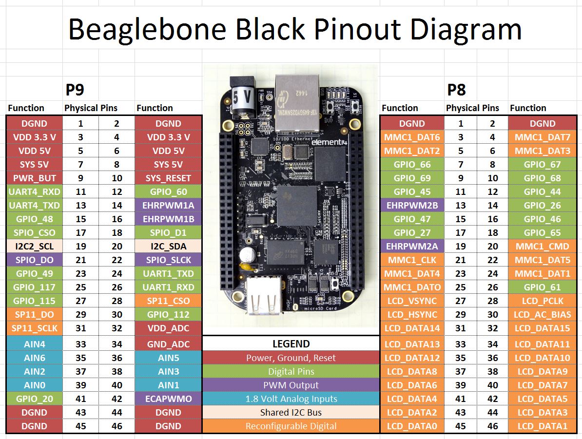
In Python, we reference pins by first specifying which header we want (P8 or P9) and then which physical Pin. For Example, to specify pin 12 on the left header, we would refer to it as “P9_12”. For digital output, we should use one of the pins above that is shaded green.

To talk to the GPIO pins in Python, we must first import a library. The latest versions of the Beaglebone Black Rev C. are shipping with the library already installed. If you have an earlier version, you need to update to the latest operating system. You can visit the beagleboard.org web site to download the latest operating system. If you get an error when you try and load the library, you know that either you have typed the command in wrong, or you need to update your operating system. In python to import the library you need to include the line:

Once you have imported the library, you then need to setup your pin as an output pin:

Now if you want to set that pin high you can use the command:

To set the pin low you can use the command:

After you are done working with the pin, you should “cleanup” to free the pin up:

These are all the commands you need in order to set the pin “HIGH” or “LOW”. Remember that in the High state, the Beaglebone Black outputs 3.3 Volts.

We can bring things together to make a simple program that will turn the pin on and off in three second intervals. Try and play around yourself with this code. Then try different GPIO pins.


Beaglebone Black LESSON 1: Understanding Beaglebone Black Pinout

This is the first in a series of lessons on the Beaglebone Black. Hopefully you have been with us through our earlier series of lessons on the Arduino, Python, and the Raspberry Pi. If you have been through those lessons learning the Beaglebone will be a snap.

If you are going to follow along with us in these lessons, you can go ahead and order your Beaglebone HERE.

To get started, we need to first of all get our mind around all the different pins. I have put together the diagram below for the default pin assignments for the Beaglebone black.

Default Pin Configuration for the Beaglebone Black Rev. C.

You can see that the Beaglebone has a large number of pins. There are two headers. Make sure you orient your Beaglebone n the same direction as mine in the picture, with the five volt plug on the top. In this orientation, the pin header on the left is referred to as “P9” and the pin header on the right is referred to as “P8”.  The legend in the diagram above shows the funtions, or the possible functions of the various pins. First, we have shaded in red the various 5V, 3.3V, 1.8V and ground pins. Note that VDD_ADC is a 1.8 Volt supply and is used to provide a reference for Analog Read functions. The general purpose GPIO pins have been shaded in green. Note some of these green pins can also be used for UART serial communication. If you want to simmulate analog output, between 0 and 3.3 volts, you can use the PWM pins shaded in purple. The light blue pins can be used as analog in. Please note that the Analog In reads between 0 and 1.8 volts. You should not allow these pins to see higher voltages that 1.8 volts. When using these pins, use pins 32 and 34 as your voltage reference and ground, as pin 32 outputs a handy 1.8 volts.  The pins shaded in light orange can be used for I2C.  The dark orange pins are primarily used for LCD screen applications.

Raspberry Pi LESSON 31: Making a Dimable LED with Python

In this lesson we are ready to bring together a lot of what we learned in earlier lessons. We will create dimable LEDs which will respond to two buttons. If one is pressed the LED will gradually grow dimmer. If the other is pressed, the LED will gradually grow brighter. This will require us to use our skills in using GPIO inputs, pullup resistors, GPIO outputs, and PWM.

For convenience we will use the same circuit we used in LESSON 30, shown below. Also, if you want to follow along with these lessons, you can buy the gear you need HERE.

This Circuit Controls two LED from Push Buttons Using the Raspberry Pi

The objective of this circuit is that we want the LEDs to grow brighter each time the right button is pushed, and we want them to grow dimmer each time to left button is pushed.

The video above steps through and explains this code.


Raspberry Pi LESSON 30: Controlling LEDs from Push Buttons

In this lesson we will show how you can control LED’s from push buttons. In order to get started, you will want to expand the circuit we built in LESSON 29 to include two LEDs. The schematic below shows how you will want to hook things up (Also, remember you can see the Raspberry Pi pinout in LESSON 25). Also, as we have mentioned before, if you want to follow along with us in these lessons you can get a kit that has all the gear you need HERE.

This Circuit Controls two LED from Push Buttons Using the Raspberry Pi

In the video lesson, we take you through the code step-by-step. We use the techniques learned in LESSON 29 to detect if a button has been pushed. We introduce two new variables, BS1 and BS2, so indicate the state of the LED’s. A BS1=False means the LED1 is off. A BS1=True means the LED is on. This concept allows us to determine whether we should turn the LED on or off when the button is pushed. Basically, we want to put it in the opposite state when a button is pushed. The code is below. The video shows how it works.


Raspberry Pi LESSON 29: Configuring GPIO Pins as Inputs

We are now ready to learn how to “read” values from the Raspberry Pi GPIO pins. In order to demonstrate this, we will show a simple example using buttons. If you ordered the Raspberry Pi kit we recommend, you already have everything you need, or you can pick your kit up HERE. To start with, you need to put together a simple circuit that connects two push buttons to your Raspberry Pi. Connect according to this schematic.

Simple Circuit Connecting Two Push Buttons to the Raspberry Pi

Note that one leg of each button is connected to the ground rail on the breadboard, that is connected to the Pi ground at physical pin 6. Then we connect the left leg of the left button to physical pin 16, and the left leg of the right button to physical pin 12.

In order to read the state of these buttons, that is, whether they are being pressed or not, we need to write a python program. To begin with we must import GPIO library and specify that we want to

 Now we are ready to set the pin modes on the pins we are using. We are using pins 12 and 16. We will set up variables so that we can reference the pins by descriptive variables.

Note in our GPIO.setup commands, we are not just defining the pins as inputs, we are also activating pullup resistors with

With this command, the raspberry pi places a pullup resistor between the designated pin and the 3.3 V rail. This means that if we simply read the pin, we will read a “1”, “True”, or “High”, since the pin will see the rail through the pullup resistor. If we connect the pin to ground by pressing a button or switch, the pin will then read a “0”, “False” or “Low” because it will be a straight connection to ground, and as current flows through the pullup resistor, the 3.3 Volts will drop across the pullup resistor. Hence, the pin sees 0 volts.

The result is that with the pullup resistor activated, the pin will always report a “1” until something connects the pin to ground, and then it will read a “0”. This configuration should work for most things, but if you are getting unpredictable results which can result from electrical noise, then try using external pullup resistors.

 Now we are ready to read the values from the pins.

Notice that we read from the pin using the GPIO.input command. Also note that for reliable results you need to usually put a small delay in your code. This will help debounce the button, and will also give more stable results.

OK, so our final code is as follows:

This code will sit and monitor the buttons, and when one is pressed it will report that that button has been pressed.