Tag Archives: Push Buttons

Arduino Tutorial 29: Using Push Buttons to Create Dimmable LED

In this lesson we show you how to create a Dimmable LED using two pushbuttons. Pressing one button will gradually increase the brightness, while pressing the other button will gradually decrease the brightness. The project also includes an active buzzer to provide the user feedback that either maximum or minimum brightness have been reached. I encourage you to try and build this yourself before watching the video. Then see if you can do it on your own, and then see if you are doing the way I do it, or if you find an alternative suitable solution.

If you want to follow along at home, you can order the Arduino Kit we are using HERE.

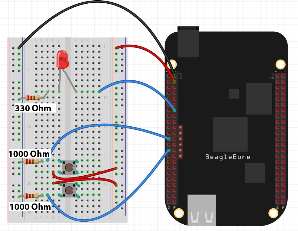
Below is the code we used to achieve the toggle operation. The video gives details on how to connect up the circuit.


Beaglebone Black LESSON 11: Dimable LED with Buttons from Python

In LESSON 10 we showed you how to create a dimable LED using the analog input from a potentiometer. In this lesson we will create a dimable LED using digital buttons. We will say we want a press of the top button to make the LED brighter, and a press of the bottom button to make the LED dimmer. In order to get going, you will need to build this circuit. If you do not already have a Beaglebone Black, you can get one HERE.

Push Buttons LED Circuit
This Circuit Controls LED Brightness from Push Buttons

In this circuit make note that we are using two 1000 ohm resistors as pull down resistors on the push buttons. It is important that these resistors be at least 1000 Ohm each. Next, notice the current limiting resistor on the LED is 330 Ohm.  We establish a ground rail on the breadboard from pin P9_2 on the Beaglebone Black. We establish our 3.3 Volt rail on the breadboard from pin P9_4 on the Beaglebone. We will use P9_14 as the PWM pin to control the LED, and we will use pins P9_23 and P9_27 as our digital input pins.

We will want a press of the top button to increase brightness and a pres of the bottom button to decrease brightness. As we discussed in Lesson 10, we want to insrease and decrease PWM signal exponentially, as this will allow the eye to perceive a smooth and linear increase in brightness.

If we want the LED to go from full off to full brightness in 10 steps, we need an equation to relate Duty Cycle to BP. BP will be a variable that will keep track of where we are. If we press the up button we increment BP by 1. If we press the down button, we decrements BP by 1. We want to start with BP=0, and the LED full off. This would be the point:

(BP,DutyCycle) = (0,0)

When the button has been pressed 10 times, we want a DutyCycle of 100%. This would be the point:

(BP,DutyCycle) = (10,100)

We now need to fit an exponential curve through these two points.

DutyCycle = C^(BP) -B

We need to figure out what the constants C and B need to be. Note DutyCycle and BP are our variables . . . they are like X and Y. We can plug our first point in and solve for B.

0 = C^0 – B

Anything raised to 0 equals 1, so the equation becomes

0 = 1 – B

B=1

Now substitute B into our equation and we get:

DutyCycle = C^(BP) -1

Now put in our second point to calculate the constant C.

100 = C^10 – 1

101 = C^10

C = tenth root of 101 = 1.5864

So, our final equation to calculate Duty Cycle is:

DutyCycle = 1.5864^(BP) – 1

With this equation we are not ready to develop our code. The video will step you through the code line by line.

Beaglebone LESSON 8: Read Button State from Python


In this tutorial we will see how to read digital values from the GPIO pins. We will be doing digital reads, which means we will be limited to “HIGH” or “LOW” readings. This is a 3.3 volt system, so we need to make sure that the “HIGH” applied signal is 3.3 volts.

Our pinout from LESSON 1 shows which pins are suitable for digital reads.

Beaglebone Black Pinout
Default Pin Configuration for the Beaglebone Black Rev. C.

It is the green GPIO pins which we can use for digital reads. In this lesson we will demonstrate the digital read technique using a simple two button circuit. In order to complete this lesson, you should go ahead and build this circuit.

Beaglebone Button
Example of Simple Beaglebone Black Button Circuit

Notice we are using Pin 1 on Header P9 as the ground and Pins 11 and 13 on header P9 s the input pins. Also note the pulldown resistors are 1000 Ohm. It is important to use at least this much resistance. If you do not have 1,000 Ohm resistors, using something larger NOT something smaller.

Once you have the circuit set up we are ready to begin programming.

First up, you need to import the GPIO library. If you have the latest version of Debian Wheezy, you should have the library on your system. If you do not have it you will need to update and upgrade your operating system. To load the library, you will use the python command:

We now need to configure out pins P9_11 and P9_13 as inputs. We do this with the command:

Now to read the state of the buttons, we would use the commands:

state1 will be True if the top button is pushed, and False if it is not being pushed. Similarly, state2 will be True when the button is being pushed, and False when it is not being pushed.

We can bring these concepts together to make the following program. Play around with the program and see what all you can make it do.


Raspberry Pi LESSON 31: Making a Dimable LED with Python

In this lesson we are ready to bring together a lot of what we learned in earlier lessons. We will create dimable LEDs which will respond to two buttons. If one is pressed the LED will gradually grow dimmer. If the other is pressed, the LED will gradually grow brighter. This will require us to use our skills in using GPIO inputs, pullup resistors, GPIO outputs, and PWM.

For convenience we will use the same circuit we used in LESSON 30, shown below. Also, if you want to follow along with these lessons, you can buy the gear you need HERE.

Raspberry Pi LED Circuit
This Circuit Controls two LED from Push Buttons Using the Raspberry Pi

The objective of this circuit is that we want the LEDs to grow brighter each time the right button is pushed, and we want them to grow dimmer each time to left button is pushed.

The video above steps through and explains this code.


Raspberry Pi LESSON 30: Controlling LEDs from Push Buttons

In this lesson we will show how you can control LED’s from push buttons. In order to get started, you will want to expand the circuit we built in LESSON 29 to include two LEDs. The schematic below shows how you will want to hook things up (Also, remember you can see the Raspberry Pi pinout in LESSON 25). Also, as we have mentioned before, if you want to follow along with us in these lessons you can get a kit that has all the gear you need HERE.

Raspberry Pi LED Circuit
This Circuit Controls two LED from Push Buttons Using the Raspberry Pi

In the video lesson, we take you through the code step-by-step. We use the techniques learned in LESSON 29 to detect if a button has been pushed. We introduce two new variables, BS1 and BS2, so indicate the state of the LED’s. A BS1=False means the LED1 is off. A BS1=True means the LED is on. This concept allows us to determine whether we should turn the LED on or off when the button is pushed. Basically, we want to put it in the opposite state when a button is pushed. The code is below. The video shows how it works.