In this video lesson we show how to use the HC-SR04 ultrasonic sensor to detect the distance to obstacles in a robotic application. We use the sensor to measure the time it takes for a ping to travel from the sensor, to the target, and then back. We use this measured time, and the known speed of sound to calculate the distance to the target. This will be used in future lessons to keep the robot from running into an obstacle.
In this lesson we explain the concept of echolocation, and how the HC-SR04 ultrasonic sensor can be used to measure the time it takes a ping to go out, bounce off a target and come back. From this ping travel time, it is possible to precisely calculate the distance to the target. For your convenience, the code we developed is included below.
HC-SR04 Ultrasonic Sensor in a Distance Measuring Project
In this lesson we strive to improve the precision of our distance measurements using an average of a large number of measurements. This builds on the work we did in the last few lessons.
We are building this with parts from our Elegoo Kit , and our actual build is using an Arduino Nano, which allows the project to be built on a single breadboard. You can get the neat jumper wires HERE.
This video takes you through the process step-by-step.
The code developed in this video is included below for your convenience.
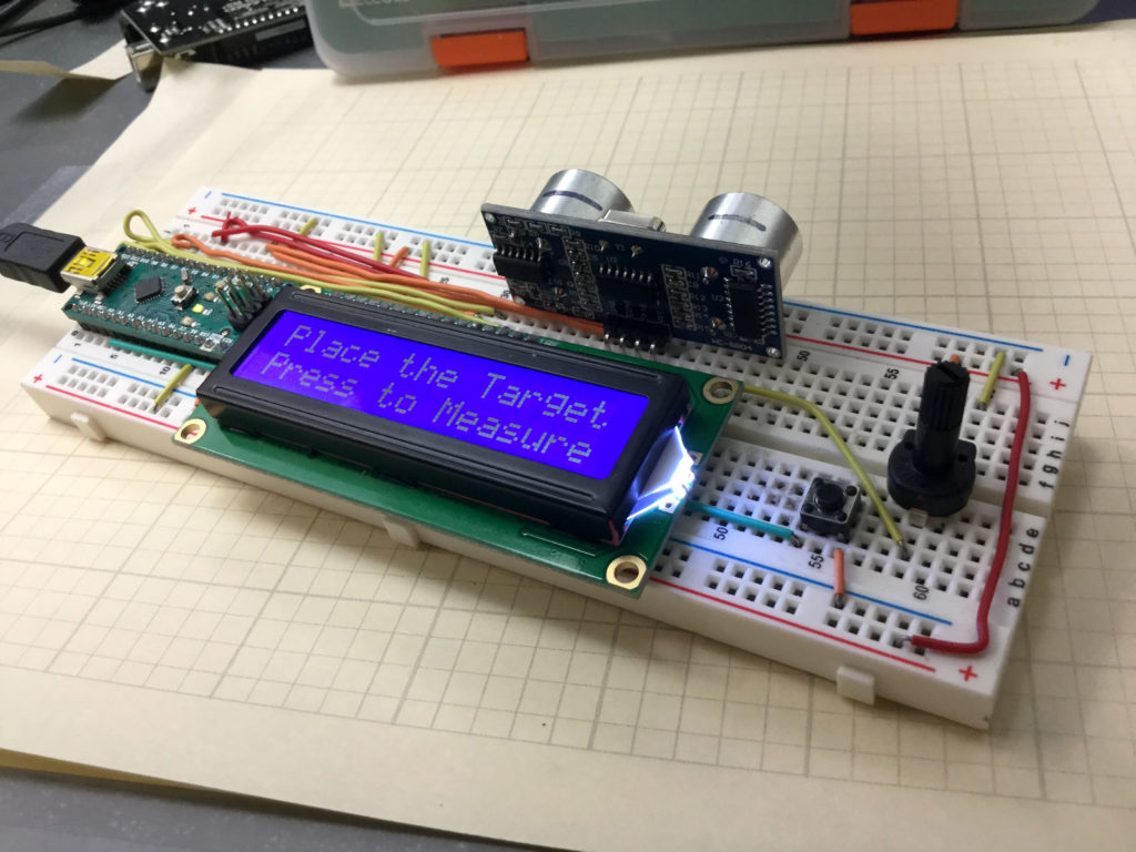
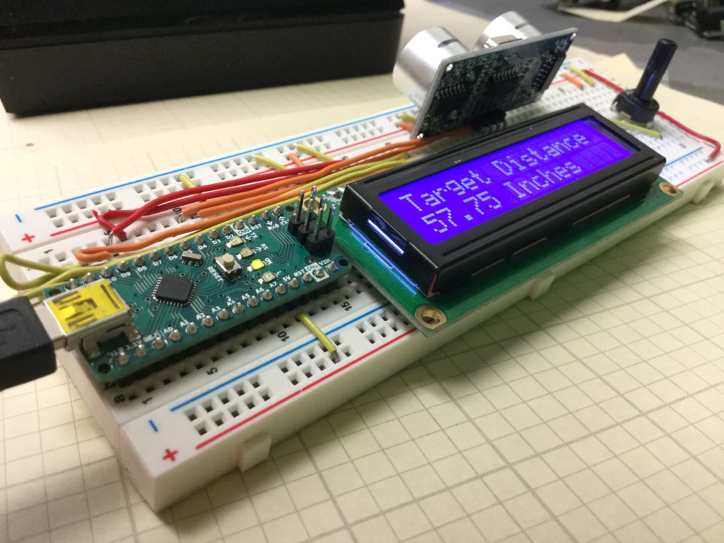
This is our completed build of a portable, ultrasonic distance sensor.
In this lesson we add a “GO” button to our portable distance measurement system. Note that from the work done in Lesson 59, we are only left with digital pin 13. The problem is that pin 13 is connected to the on-board diode, so trying to use pin 13 as a button pin will not work.
Never fear we can use one of the analog in pins. To use an analog in pin as the button pin, in the void setup, you need to declare the pin as an INPUT, and then digitalWrite the pin to HIGH. This will connect it to 5V through a pullup resistor. Now you just have to do a digital read to that pin. When button is untouched, you will read a “1”, and when you press the button, you will read a “0”.
We are building this with parts from our Elegoo Kit , so if you get this kit, you will be using the same hardware we are using.
A challenge with this project is to keep the build neat and compact, which is much easier if you use an Arduino Nano, which allows the project to be built on a single breadboard. The build neatness is also facilitated by using small straight jumper wires, which you can get HERE.
This video takes you through the explanation step-by-step:
This is our completed build of a portable, ultrasonic distance sensor.
This Lesson picks up where Tutorial 55 left off. You want to take the basic distance measurement capability you built, and make it portable. In order to make it portable, you will need to add an LCD display, and figure out a way to power it. The easiest way to get portable power is to connect the Arduino to a USB power bank.
The sensor is part of our Elegoo Kit , so if you get this kit, you will be using the same hardware we are using.
A challenge with this project is to keep your build nice and neat, as there are lots of connections, and if any are not completely secure, you will get unpredictable performance in your device. For this build we will be using an Arduino Nano, which allows the project to be built on a single breadboard. You can use the Arduino Uno if you do not have a Nano, and things will work out the same. The build neatness is also facilitated by using small straight jumper wires, which you can get HERE.
The first task will be to lay out your components in preparation for the build. Carefully consider all the connections you will have to make, and then organize so that the connections can be made with minimum confusion. This means minimize the number of crossing wires, and try to have needed connections in the same general area.
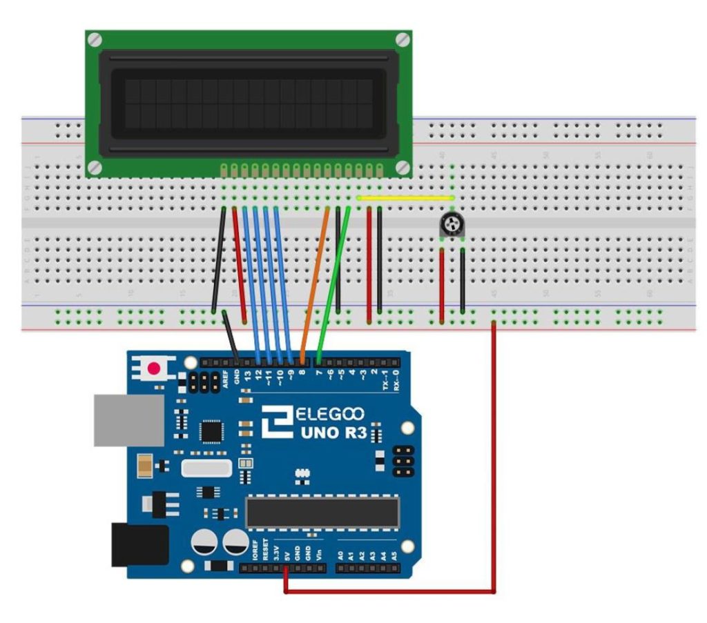
The LCD will need to be wired up according to the following Schematic:
This schematic will allow you to connect the LCD to the Arduino
Now, you will also need to connect the HC-SR04 Ultrasonic Sensor.
HC-SR04 Pin
Arduino Pin
VCC
5 V
GND
GND
Trig
digital 2
Echo
digital 3
This video takes you through the build and programming step-by-step.