9-Axis IMU LESSON 3: Understanding How Accelerometers Work

Accelerometer
This photo shows a conceptual schematic of how an accelerometer works.

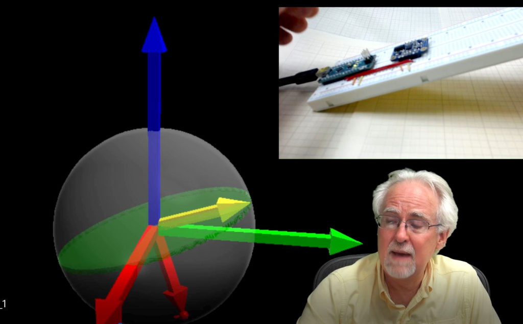
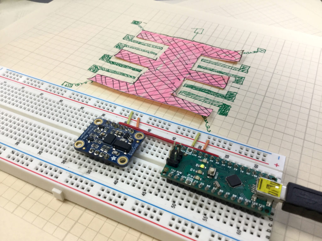
In this lesson we describe how the acceleromters on chips like the Adafruit BNO055 work. They work based on microscopic masses suspended on springs on the chip. As the chip moves, the suspended masses respond to the motion, and the gaps between the suspended masses and the substrate changes. The chips detect these changes in position by monitoring the capacitance between the suspended mass and the substrate, or between the suspended masses and carefully designed interdigitated fingers between the mass and the substrate. C=eA/d, e is the dielectric constant of the material, A is the area of the capacitor, and d is the gap between the two capacitor plates. Changes in measured capacitance come from either a change in A or a change in d. Both d and A change in response to motion, so by monitoring the capacitance of the suspended mass, acceleration can be inferred. The video below explains clearly how this works.

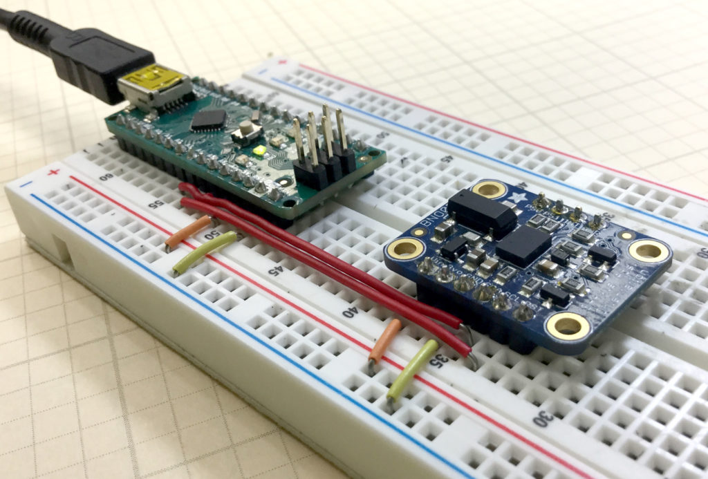
Code for Getting Raw Acceleration Data from the BNO055 9-axis Inertial Measurement Sensor.

The code below is for demo purposes only, and should not be used in any real applications. It just demonstrates how to work with this sensor in benchtop presentations.

Arduino Tutorial 25: Understanding Photoresistors and Photo Detectors


In this lesson we learn how to use photoresistors. A photoresistor is a semiconductor material. In the darkness, it has almost no free electrons, so its resistance is very high. When light shines on the device, electron hole pairs are created, and these electron hole pairs are free to conduct electricity. This lowers the resistance of the material. The brighter the light, the more electron hole pairs that are generated, and hence the lower the resistance. Hence, the resistance of these devices is inversely proportional to the brightness of the light. By hooking a photoresistor in series with a fixed resistor, the current will change as the resistance of the sensor changes. This leads to a measurable change in the voltage across the series resistor. Hence, by measuring this voltage, you get a signal that is proportional to the light. This can be read via an analog pin on the Arduino, and then the arduino can be programmed to do different things based on the brightness of the light. In this simple project we have a red LED and a green LED. If the light is on, the green LED is turned on. If the light is off, the red LED is on.

If you want to follow along at home, you can order the Arduino Kit we are using HERE.

The nice digital voltmeter used in the lesson is available HERE.

Below is the code we developed in this video lesson above.


IMUl 9-Axis IMU LESSON 2: Connecting and Getting Raw Data from the BNO055 9-Axis Sensor

BNO055
Adafruit BNO055 9-axis Sensor Connected to an Arduino Nano

In this tutorial we show you how to get raw sensor data from the Adafruit BNO055 9-axis sensor. We are using an Arduino Nano, since it allows for neat, compact builds on a breadboard. The sensor can provide acceleration along x,y and z axis, rotational velocities around x, y and z axis, as well as the strength of the earth’s magnetic vector along the sensor’s x, y, and z axis. The sensor can do a lot more than this, but to get things started, we will show you how to get these raw sensor readings from the device.

The video shows you how to connect the sensor, and below we include the code developed in the video. We strongly suggest you type the code in yourself, as you follow along with the video. You will never learn how to develop projects on your own, if you just copy and paste my code.

The code below is for demo purposes only, and should not be used in any real applications. It just demonstrates how to work with this sensor in benchtop presentations.

Arduino Tutorial 24: Understanding Passive Buzzers

In this lesson we show you how to incorporate sound into your project using a passive buzzer. Passive Buzzers have the advantage that they are less expensive than active buzzers, and you can more precisely control the tone. This lesson will show you how to hook up the buzzer, and then how to code the arduino to produce different tones.

If you want to follow along at home, you can order the Arduino Kit we are using HERE.

9-Axis IMU LESSON 1: Introduction to Nine Axis Sensors and Inertial Measurement Units with Arduino

IMU Visualization
This picture shows out 3D visualization of sensor data coming from the

In this new tutorial series we will take you step by step through creating a 9-axis IMU capable of monitoring an object’s orientation in 3 dimensional space. In this first lesson we introduce you to IMU and 9-axis sensor basics, and outline the gear we will be using in these lessons. To play along at home, you will need an Arduino Nano, and an Adafruit BNO055 Inertial Measurement Sensor.