LESSON 16: Controlling a Servo with Arduino

Its time to get moving! In this project we show you how to get things moving with Arduino. You will need an arduino, a servo, a potentiometer and some wires. If you have the sparkfun inventor kit, it has everything you need (You can pick up the inventor kit HERE).

Servo Arduino
Circuit for controlling a Servo from the Arduino using a Potentiometer

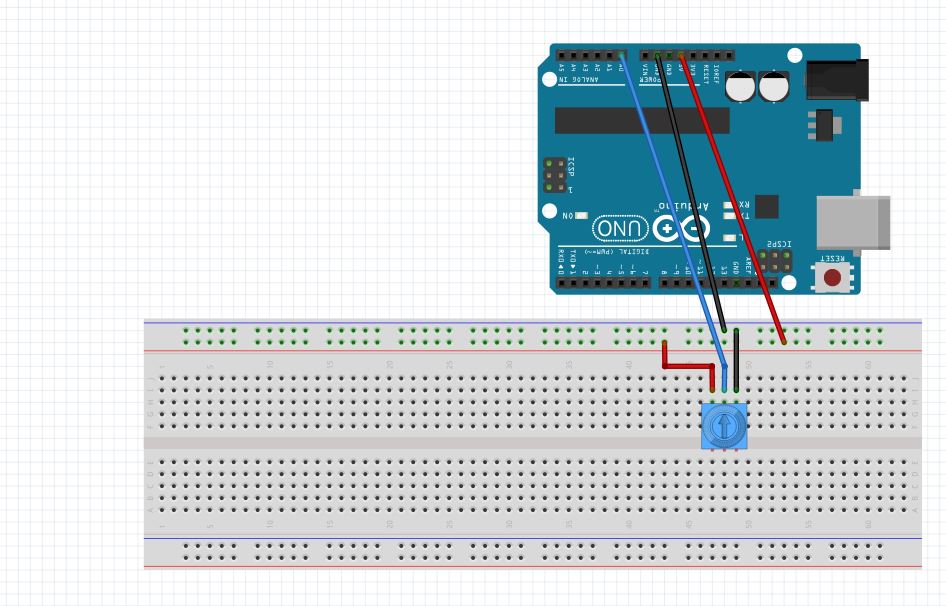
For this project, our objective is to control the position of a servo based on the setting of a potentiometer. The servo should “track” the position of the potentiometer. In order to do this, we will need to start with our Voltage Divider Potentiometer circuit from LESSON 10. In addition, we will need to hook the servo up. for the servo in the sparkfun kit, it has three wires . . . red, white, and black. The red line is for power, so it should be hooked up to 5V from the arduino. The black line is ground, and should be hooked up to ground on the arduino. The white line is the control line, and it should be hooked up to one of the arduino pins with a squiggly line.  For this example, I am using pin 9. The small servo that comes with the sparkfun kit can be powered directly from the arduino. Understand that many servos draw lots of power, and require a separate power supply, and just the control line connects to the arduino. Realize that you must be careful and not hook a larger servo to the arduino for power, as that can damage your arduino. The one in the sparkfun kit can be driven by the arduino without a problem.  Also, some servos have a different color code on the wires. Many have red/orange/brown wires. For many of these types, the red is for power, the orange is for the control line, and the brown is for ground. Be sure to check the instructions on your servo to verify the color code.  As a reminder, this is circuit diagram for the potentiometer, which you will be using in this project.

Potentiometer
This simple circuit allows you to create a voltage divider with a potentiometer, which we will use to set position of the Servo.

Most servos are designed to be operational in a range from 0 degrees to 180 degrees. The truth is though, that most will not operate over that full range. Also, you need to know that overdriving the servo beyond the range it wants to be in can damage both your arduino and your servo. Each servo is different, and sometimes two servos with same model number from the same manufacturer will have different ranges. Especially in the cheap ones (like in the sparkfun kit) have very different ranges.

So before going to far in any project you need to determine the range that your particular servo will operate in. In order to do this we need to write a simple program that will move the servo. In order to control the servo from the arduino, there are several things that must be done. The first is that you must “load” a library. A library is a special set of code written by the folks who make or sell the device in order to make it easier for you to work with. Libraries allow us to work with components in a more intuitive way. For the servo, you need to load the servo library, which comes with the arduino software you originally downloaded. To load the library, you need the following code at the top of your program:

Then, you need to create a servo “object”. This object will then be something you interact with to make the servo move. You can all the object anything you want, but I think I will call mine “myPointer” since I am going to make my servo point at things. The code to create the servo object would then look like this:

OK, now to make the servo go to a certain position, I would just have to issue a command like this:

This command goes to ‘pos’ which should nominally be between 0 and 180.  But remember that most servos will not go over that full range, so we will need to play around to see what range our servo can safely achieve. Also, the short 15 millisecond delay after moving the servo gives it time to get there and settle down. Never try and write the servo faster than it can naturally move.

The one other thing you need to do is let the arduino know which pin the servo is connected to for the control line. We are using pin 9, and will set up a variable at the top of the code to set servoPin=9, but it can be any pin that can analogWrite (one with a squiggly line).  To tell your arduino where the servo is connected, for the case of my servo which I names myPointer, the following code should be put in the void setup:

What you need to do now is write a program that will input the user for a position, and then write that position to the servo. The purpose of this is to determine the natural range of your particular servo. You should write this program yourself, but if you get stuck you can look at my code below. You should use this as a help if you need it, but your should not cut and paste it. Write your own code!

OK, with this code we should see the arduino prompt the user to a position and then write that position to the servo. The thing to do with this code is play around and figure out what range of motion your arduino can achieve. If you arduino sits and twitches, you have probably overdriven it. Keep playing with the numbers until you determine the range your servo can sweep to without jittering.

Once you know that range, you can play around with the code and the servo. Create a program that will smoothly sweep the servo through its range of motion. For my servo, I created the following code. Again, play with it yourself, and use this code only if you get stuck. Also, realize that my servo operates from 15 to 170 degrees, so that is why I used those numbers. You need to determine the range of motion for your servo, and use those numbers in the program.

 Now we need to write a program that will set the position based on the position of the potentiometer. We want the servo to point to the left if the potentiometer is positioned all the way to the left. Similarly we want the servo to point to the right if the potentiometer is all the way to the right. We need to do the math carefully to make sure that we do not try and overdrive the servo.  You must assume the user has no knowledge of servos and will turn the potentiometer to any position. In order to make sure the servo is not over-driven, you must carefully do the math. For this case, what is the independent variable? It is the number coming off the potentiometer. That is what you or the user “sets”, that is the independent variable, that is the horizontal axis. Now, what is the dependent variable? That is the pos (position) number. That is what you want to calculate from the independent variable. To do the math, think about the two points you know. You know that the potentiometer reads from 0 to 1023. You know that for my servo (yours will be different) the range of useful motion is from 15 to 170. So, when the potentiometer is set to 0 we want the position to be 15. There, you have one point, the point (0,15). Now we also know that when the potentiometer reads 1023, we want to position the servo at 170. So, now we have another point, the point (1023, 170). Now we have two points and can create the equation that will allow us to calculate the Pos based on the reading from the potentiometer. You should be able to do this by yourself now, but if you get stuck you can look at my notes. Remember, you need to do it for your values of useful range on the servo, not my numbers of 15 and 170.

linear equation
This shows the math to on how to calculate servo position based on potentiometer reading

So with this equation you can now calculate a pos for the servo based on the reading from the potentiometer. You should be able to write the code now to control the servo position from the potentiometer. If you get stuck watch the video that provides step-by-step directions on the code.

LESSON 15: Super Cool Arduino Color Sensor Project

This first video shows just the results of this extremely exciting project!  Watch the first video if you want a quick summary showing the working project.

The second video, below shows an in depth step-by-step tutorial on how to make the project work.

OK, in the first 14 lessons we were laying the ground work for circuits and programming. Now it is time we had a little fun. This project will show you how to do an insanely cool circuit based on what you have learned already. This time we are going to use the RGB LED circuit you worked on in Lesson 13 and Lesson 14,  but this time you will set the color based on the color seen by a color sensor! That is right, we will incorporate a color sensor into the circuit. If the color sensor sees red, the LED will turn red. If it sees blue, the LED will turn blue. Our challenge in this project is to make the sensor match as many colors as well as possible.

Arduino Color Sensor
We will use an arduino color sensor to set the color of the RGB LED

There are a couple of things you will need for this project in addition to the arduino, breadboard, and RGB LED we have been using so far. The good news is the components are very affordable and can be easily ordered from amazon. First up you will need the Virtuobotix Color Sensor which you can order HERE. To connect the color sensor to your arduino you will need some male/female connecting wires, which you can order HERE.  You probably have the rest of the things you need, but I will give a complete list at the end of this lesson.

For the LED side of things you will want to use the same circuit from Lesson 13 and Lesson 14.  As a refresher, here is the schematic;

RGB LED Circuit
Circuit used to control RGB LED from an arduino

Now for this project, instead of getting the desired color from the user via the serial port, we will set the LED color by having it match colored cards we place in front of the sensor. So, we will need to figure out how to operate the sensor. It is really pretty straighforward. First up, we have to hook it to the arduino. That is probably easiest done by following this table, rather than me trying to draw a picture:

Connecting the Color Sensor to the Arduino

Color Sensor Pin
Arduino Pin
S0GND
S15V
S2pin 7
S3pin 8
OUTpin 4
VCC5V
GNDGND

Hopefully that is clear. Remember, you must use the male/female wires described above to connect the Color Sensor to the Arduino. Unfortunately, the sensor is too big to connect to a standard size breadboard. Use the table above to carefully make the connections, but after you are done your circuit should look like this:

Color Sensor
Color Sensor and RGB LED connected to the Arduino

There are lots of wires, so double check your work against the table above.

Now,  this is the way the senor works. It will make three different readings indicating the relative “strength” of the three primary colors  . . . Red, Green and Blue.  Never fear, if you know the strength of the primary colors, you can figure out any color as they will just be different “mixes” of red,  green and blue.

Which color is read depends on the voltages you write to the S2 and S3 pins, according to this table:

S2
S3
Color Read
LOWLOWRed
LOWHIGHBlue
HIGHHIGHGreen

To actually make a measurement, you need to select which color strength you want to read by doing digital writes to pins S2 and S3 according to the pins above. Then you read the color strength on the sensor OUT pin, which we have connected to Arduino pin 4. To make the measurement, you need to make a pulseIn measurement at pin 4 on the arduino. The pulseIn measurement is an arduino command that looks at the pin you specify, and looks for a pulse, and returns to you a number representing the length in microseconds of the pulse seen at the pin specified. For example, lets say we already declared a variable pulseWidth to hold the measured value. The following code would allow us to measure the pulseWidth at the outPin (make sure you have declared both variables, and you should set the pinMode of outPin to be an INPUT,  since you are reading from it;

 This measurement will return a value between 0 an 102,400. Because of this, you need to be sure to declare pulseWidth variable an unsigned int. Normal integers can only hold numbers up to +/- 32,768 an unsigned int allows only positive numbers but allows numbers up to 4,294,967,295. 

The number that is returned which we put in the variable pulseWidth above can be interpreted as such: The lower the number, the stronger the color being read. The larger the number, the weaker the color.

We need to somehow convert this rather odd number into something that means something in the real world. Well, when we write values to an RGB LED we want them to be between 0 and 255.  Also, that is a fairly standard scale to report RGB colors . . . by giving the relative strength of the compoents of R, G, and B on a scale from 0 to 255. First we need to convert 0 to 102,400 to this range.  102,400/400 = 256. Almost exactly what we want! But we need to subtract one. So, we could say that rColorStrength = (pulseWidth/400) – 1. That gets us a number between 0 and 255. Only problem is, remember that in the original pulseWidth, big numbers mean weak colors and small numbers mean strong colors, so we need to fix that. We could fix it by now saying:

rColorStrength = (255 – rColorStrength);

That simply adjusts things so that big numbers now mean strong colors. Also, you can see this example would be for reading red. You would need to repeat by setting S2 and S3 to also create gColorStrenght and bColorStrength for green and blue.

So, with this little bit of math we should have what we need to actually read R, G, and B values that fairly accurately represent the color the sensor is seeing. In the video I go through the code. I am not posting the code on this one because you need to think through it and if you get stuck, the video shows you each step.

LESSON 14: If Statements and Conditionals in Arduino

In our LED project in Lesson 13, we controlled the color of the LED by changing lines of code in the program. As you know, you really want to do that sort of thing by interacting with the user over the serial port. So, in this project, we are going to have the user set the color by indicating his preferred color in the serial monitor. Notice in our new picture below we have covered the LED with a ping pong ball. We did this so the LED will show better in the video, but after doing it, I really like it! It makes a cool little lamp. You can do this by creating a small hole the size of the LED in the ping pong ball, and then just mounting the ball on the LED. Cool stuff!

RGB LED
We have added a ping pong ball to the top of our RGB LED.

This project uses the same circuit we set up in Project 13. We will just be changing the code.

RGB LED Circuit
Circuit used to control RGB LED from an arduino

So, for this project, we will want the user to input his desired color for the LED. Then we will make the LED change to the color he requested. In order to do this, we need to learn a new programming command called the if statement. The if statement has a clause, or group of commands between a set of curly brackets. It executes those commands only if a condition is met. An if statement in arduino would look like this:


The commands between the curly brackets will be executed if the condition inside the parenthesis is true. Lets consider you had two variables, a and b. Lets say you only wanted to execute the commands in the clause if a is > or = to b. In that case you would put that condition in the parenthesis and your code would look like this:

The arduino would only execute the code if the condition was true. Otherwise it would jump to the first line of code after the closing curly bracket. There are a number of different condition tests that can be used in the parenthesis:

You can combine more than one condition by using the logical operators “and” or “or”. In arduino the symbol for “and” operation is && and the symbol for “or” operator is ||. (This is the symbol above the backslash on the keyboard). So you could have a condition where a is greater than b AND a is greater than c. This would look like:

 OK, so that is how if statements and conditional work. A key thing is that you have to remember than when you are testing for equality in an if statement, you use two equal signs. One of the common mistakes I see students make is to forget and just use one equal sign in a conditional.

What you will want to do now is write a program that will ask the user what color he would like the LED to be. In the prompt let him know that his choices are Red, Green, or Blue. Then turn the LED that color. You should also include a “test” . . . if he does not choose one of the allowed choices, he must choose again. Do your best to develop the code on your own, but if you get stuck, peak at my code below. You should not copy and paste my code, but just use it as a guide if you get stuck.

 OK, now your assignment is to move forward and have the program have more options for colors. Have it where you can turn the LED Red, Green, Blue, Cyan, Magenta, Yellow, Orange, Purple, Pink. Do some research on the internet to make sure you are really hitting these colors. Part of your grade will be how well you match the colors.

LESSON 13: Controlling RGB LED with Arduino

OK, we are ready to move forward and learn new circuit skills and new programming skills. In today’s lesson we will learn how to control an RGB (Red, Green, Blue) LED with an arduino microcontroller! This will introduce us to a new circuit component, and will require us to learn some new programming skills.

RGB LED
Circuit to control RGB LED with an Arduino

An RGB LED is basically three LED’s in one. It has 4 leads. One lead, the long lead, is the common ground. Then one lead controls the red LED, one lead controls the green LED, and one lead controls the blue LED. All three of the LED’s are connected to ground through the same pin. You can control the color you get out of the LED based on the voltages you write to the different control pins. A schematic will probably help you understand how the component works and how you should hook up to it.

RGB LED
This schematic shows how to work with a common cathode RGB LED

This picture shows the four pins for a common cathode RGB LED. “Common Cathode” just means that the LED’s share the ground pin. There are also “Common Anode” LED’s which share a common high voltage pin, and then each color has its own ground. I think these are much more confusing, but just mention them so that you know that this tutorial is for the common cathode type.  The Sparkfun Inventor Kit has the common cathode configuration, which is the type I prefer. Also note in the drawing you can see that the length of the pins is your clue as to which pin controls red, which green and which blue.

Now lets think about using this in a circuit. As you can see in the schematic, all three of the LED’s share a common ground pin. You can easily see that pin should be connected to your circuit ground. Now, think about how you would connect the control pins. To control a normal LED, you needed to connect to one arduino output pin. To control this LED, how many control pins will you need to use on the arduino? That’s right . . . you will need three control pins. Also, remember than you never connect an LED directly to a voltage source, you always use a series current limiting resistor (typically 330 ohms). For these new RGB LED’s how many current limiting resistors will we need? We will need three . . . each color control pin will need its own current limiting resistor. So each color control pin will connect to an arduino output pin through its own current limiting resistor. Once that is hooked up, we can control what color the LED is by writing voltages from the arduino to specific legs of the RGB LED. If we write a voltage to the red pin, the LED will be red. If we write a voltage to the blue pin, the LED will be blue. Also the exciting thing is that if you write voltages to multiple pins, you can get the in between blended colors. Basically by analogWrite-ing different values to the 3 different control pins, you can get any imaginable color. But first, lets go ahead and get our circuit set up. The following schematic controls red from arduino pin 6, green from arduino pin 10 and blue from arduino pin 11. Go ahead and hook this circuit up.

Arduino RGB LED circuit
Arduino circuit to control the color of an RGB LED.

Now lets play around with a program that will independently turn on the different colors. We will start simple so we can get an intuitive feel for how the LED works.

 With the code above, what color do you anticipate the LED will be? Hook up the circuit and type in the code, and see what happens. It is important that you type in the code. Do not cut and paste my code. You need to type it in. When you type it in, you will probably make mistakes and when you do you will have to troubleshoot or debug your code. That means you have to find your mistakes. All programmers make mistakes, and it is important very early on to learn how to find your mistakes.

Modify the code above so that the LED turns green.

Now modify it again so that the LED turns red.

Now try for the in between colors. How would you get the LED to turn orange? Play around with achieving different colors. Try to get the following colors:

Cyan

Magenta

Yellow

Orange

Purple

LESSON 12: Simple and Easy Way to Read Strings, Int’s and float’s Over Arduino Serial Port

One of my biggest frustrations in programming is the confusion over inputting data over the serial port. There are lots of Arduino tutorials that make it much harder than it has to be. There are many difficult and complicated ways you can read data over the serial port, but luckily there is an easy way. While we touched on this briefly in earlier videos, it is such an important topic I want to focus on it in this lesson.

In order to read data over the serial port,  you first have to determine what type of data you will be expecting. Almost all possible needs can be covered by three simple data types. Usually you can make just about any project work with Strings, Float’s, or Int’s. So, you need to know how to read these three data types over the serial port. The easiest way to read a string of text is using the Serial.readString() command. The easiest way to read a Float is with the Serial.parseFloat() command and the easiest way to read in Int with with the Serial.parseInt() command.

To practice this, lets do the following. Write a program that will promt the user for his age, for how much he weighs, and then how tall he is in feet. Then print out a nicely formatted output that relays that information back to the user.

In order to do this the first thing we must do is decide what type of variables to use for each of these three pieces of data.  For the person’s name, you naturally would use a String, since a name is a string of text. To store the weight, we would just about always round to the nearest whole number so it would make sense to use an Int for this. On height, we would not normally round to the nearest foot . . . we might want to say that someone was 5.5 feet tall. In this case we should use a float, since we want the decimal numbers. So, we would then declare these variables the suitable type and then read them in using the corresponding commands.

Also, remember when you are going to read data from the serial port you must do three things: 1) Prompt the user for data, 2) wait for him to input the data, and 3) read the data. This should be review as we have done this in several earlier lessons.

Try and write the program yourself, but if you get stuck you can look at the code below that I wrote for this problem.

OK, hopefully you were able to get this working. Now time for you to go solo and write a program on your own.

Prompt the user for his name, and his weight in pounds. Then use that to calculate his weight in Ounces, in grams, and in carats. Note, that is carats, like they measure diamonds, not carrots like you eat.

After doing these calculations send a message to the user greeting him by name and telling him is weight in pounds,  in ounces, in grams,  and in carats.

In order to do this assignment you will have to do some research to figure out how to do the conversions.